
An automatic edge banding device for furniture panels

An edge banding device and plate technology, applied in the direction of grinding drive device, adhesive application device, grinding/polishing safety device, etc., can solve the problems of width limitation, inconvenient operation, uneven edge banding, etc., and achieve increased adhesion , Low power consumption, high linkage effect

Active Publication Date: 2020-06-19
山东朝泰实业有限公司
View PDF12 Cites 0 Cited by
  • Summary
  • Abstract
  • Description
  • Claims
  • Application Information

AI Technical Summary

Problems solved by technology

[0002] The traditional edge banding work of furniture boards is realized by automatic edge banding machines, but the existing automatic edge banding machines need manpower to push the furniture boards into the device, and the device can drive the boards to automatically move backwards and start to apply glue to the boards. It is inconvenient to operate and is limited by the width of the board. Secondly, the board is moved backward through the rotation of the traction wheel in the device. The fixing of the board is unstable, and the glue coating and edge banding work will cause damage to the board. Extrusion is used to enhance the adhesion force between the edge banding strip and the board, but the force of extrusion will push the board to move horizontally, which will cause the joint between the board and the edge banding strip to be weak. Secondly, the traditional edge banding device will push the edge banding It is directly bonded to the board through the edge banding glue. The wood chips or unevenness on the board will cause the edge banding to be uneven, and the edge banding strip is easy to fall off

Method used


Image

  • An automatic edge banding device for furniture panels
  • An automatic edge banding device for furniture panels
  • An automatic edge banding device for furniture panels

Examples


Embodiment Construction

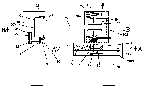
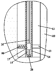
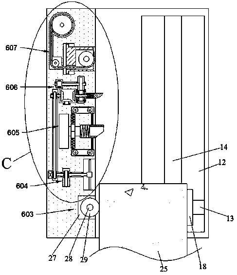
[0026] Combine below Figure 1-Figure 9 The present invention is described in detail, and for convenience of description, the orientations mentioned below are now stipulated as follows: figure 1 The up, down, left, right, front and back directions of the projection relationship itself are the same.

[0027] The present invention relates to an automatic edge sealing device for furniture panels, which is mainly used for wood edge sealing. The present invention will be further described below in conjunction with the drawings of the present invention:

[0028]An automatic edge banding device for furniture boards according to the present invention includes a body 10, four support columns 11 are fixed on the lower end surface of the body 10, and an introduction cavity 12 is arranged inside the body 10, and the introduction cavity 12 An introduction device 601 is provided inside, and a clamping device 602 is provided on the upper side of the introduction device 601. The plate 25 is ...


PUM


Abstract

An edge sealing device for automatically introducing furniture panels disclosed by the present invention includes a machine body, four support columns are fixed on the lower end surface of the machine body, an introduction cavity is provided in the body, and an introduction device is provided in the introduction cavity. A clamping device is provided on the upper side of the introduction device, and a plate is clamped in the clamping device. A grinding device is provided on the left side of the introduction cavity, and the grinding device includes a grinding wheel. The rear side of the grinding device is provided with a wind force device, the invention uses the guide device and the clamping device to drive the plate to carry out the edge banding operation, and the plate is followed by side grinding, sawdust removal, application of edge banding glue and edge banding strips to complete the process of plate edge banding, Secondly, the start and stop of the device is controlled by the movement of the plate, which avoids the waste of materials used for edge banding, and the edge banding of the plate is stable.

Description

technical field [0001] The invention relates to the technical field of board edge banding, in particular to an automatic edge banding device for furniture boards. Background technique [0002] The traditional edge banding work of furniture boards is realized by automatic edge banding machines, but the existing automatic edge banding machines need manpower to push the furniture boards into the device, and the device can drive the boards to automatically move backwards and start to apply glue to the boards. It is inconvenient to operate and is limited by the width of the board. Secondly, the board is moved backward through the rotation of the traction wheel in the device. The fixing of the board is unstable, and the glue coating and edge banding work will cause damage to the board. Extrusion is used to enhance the adhesion force between the edge banding strip and the board, but the force of extrusion will push the board to move horizontally, which will cause the joint between ...

Claims


Application Information

Patent Timeline
Patent Type & Authority Patents(China)
IPC IPC(8): B27N7/00B27D5/00B27G11/00B24B7/28B24B47/12B24B55/06
CPCB24B7/28B24B47/12B24B55/06B27D5/003B27G11/00B27N7/00
Inventor 胡金霞
Owner 山东朝泰实业有限公司
Learn More