
A Method of Angular Velocity Control of Permanent Magnet Synchronous Motor Using Adaptive and Direct Feedback Compensation

A permanent magnet synchronous motor and angular velocity technology, which is applied in the direction of motor generator control, electronic commutation motor control, control system, etc., can solve the problem of low control accuracy, and achieve improved accuracy, high engineering practical value, and good performance. sticky effect

Active Publication Date: 2021-07-02
ZHENGZHOU UNIVERSITY OF LIGHT INDUSTRY
View PDF0 Cites 0 Cited by
  • Summary
  • Abstract
  • Description
  • Claims
  • Application Information

AI Technical Summary

Problems solved by technology

[0006] The purpose of the present invention is to provide a method for controlling the angular velocity of a permanent magnet synchronous motor using self-adaptive and direct-feed compensation, and then at least to a certain extent overcome the problem of low control accuracy caused by the limitations and defects of related technologies

Method used


Image

  • A Method of Angular Velocity Control of Permanent Magnet Synchronous Motor Using Adaptive and Direct Feedback Compensation
  • A Method of Angular Velocity Control of Permanent Magnet Synchronous Motor Using Adaptive and Direct Feedback Compensation
  • A Method of Angular Velocity Control of Permanent Magnet Synchronous Motor Using Adaptive and Direct Feedback Compensation

Examples


Embodiment Construction

[0067] An example embodiment will now be described more fully with reference to the accompanying drawings. However, an example embodiment can be implemented in a variety of forms, and is not to be construed as being limited to the examples described herein; in contrast, the present invention will make the present invention will be more comprehensive and complete, and the concept of an example embodiment is fully conveyed A technician in the art. The features, structures, or characteristics described may be incorporated in one or more embodiments in any suitable manner. In the following description, there is provided a number of specific details to give a sufficient understanding of the embodiments of the present invention. However, those skilled in the art will appreciate that one or more of the present invention may be practiced, or other methods, components, devices, steps, and the like can be practiced. In other cases, it is not described in detail or described in detail to avo...


PUM


Abstract

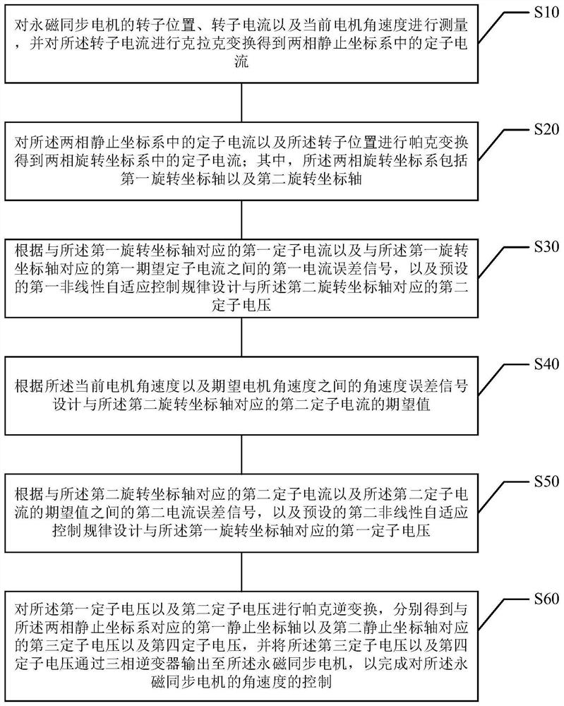
The invention provides a method for controlling the angular velocity of a permanent magnet synchronous motor using self-adaptation and direct-feed compensation, and relates to the technical field of motor design and control. The method includes the following steps: performing Clarke transformation on the stator current to obtain the stator current in the two-phase stationary coordinate system and Parker transform the stator current in the two-phase stationary coordinate system and the rotor position to obtain the stator current in the two-phase rotating coordinate system; design the second one according to the first current error signal and the first nonlinear adaptive control law Stator voltage; design the expected value of the second stator current according to the angular velocity error signal; design the first stator voltage according to the second current error signal and the preset second nonlinear adaptive control law; use the third stator voltage and the fourth stator voltage The voltage is output to the permanent magnet synchronous motor through the three-phase inverter to complete the control of the angular velocity of the permanent magnet synchronous motor. The invention improves the accuracy of controlling the angular velocity of the permanent magnet synchronous motor.

Description

Technical field [0001] The present invention relates to the field of motor design and control technology, and in particular, a method of adapting an angular magnet synchronous motor angular velocity control using adaptive and direct feed. Background technique [0002] Permanent magnet synchronous motors are increasingly widely used in servo systems that are relatively high in control performance due to its simple structure, reliable, wide-speed range, and efficiency. [0003] With the development of microprocessors, the intelligent control of permanent magnet synchronous motors is achieved by complex algorithms, and it has also caused more and more research and development personnel in recent years. Due to the change of the permanent magnet synchronous motor, the rotational inertia also changes in a large change; and when used in different environmental conditions, the friction coefficients also change. [0004] Therefore, in the conventional relying on exact model parameters, it...

Claims


Application Information

Patent Timeline
IPC IPC(8): H02P21/06H02P21/22
CPCH02P21/06
Inventor 付金华徐洁景志勇雷军委李恒
Owner ZHENGZHOU UNIVERSITY OF LIGHT INDUSTRY
Learn More