
Special hydraulic hoisting casting device for steel mill metallurgy

A metallurgical and hydraulic technology, applied in hoisting devices, hoisting equipment braking devices, cranes, etc., can solve problems such as the lack of stability of the ladle, avoid the risk of molten steel overflow, protect equipment damage, and avoid splashing out effect

Pending Publication Date: 2019-12-03
HENAN BAOQI HUADONG CRANE
View PDF0 Cites 0 Cited by
  • Summary
  • Abstract
  • Description
  • Claims
  • Application Information

AI Technical Summary

Problems solved by technology

[0004] The purpose of the present invention is to provide a special hydraulic lifting and casting device for steel plant metallurgy, which solves the problem that the stability of the steel ladle cannot be guaranteed in the prior art.

Method used


Image

  • Special hydraulic hoisting casting device for steel mill metallurgy
  • Special hydraulic hoisting casting device for steel mill metallurgy
  • Special hydraulic hoisting casting device for steel mill metallurgy

Examples


Embodiment Construction

[0029] The present invention will be further described below in conjunction with the accompanying drawings. In this embodiment, the direction of the first track is horizontal to represent the Y-axis direction in the space coordinate system, and the direction of the second track is vertical to represent the space In the X-axis direction in the coordinate system, the direction of the third track is vertical, so as to represent the Z-axis direction in the space coordinate system.

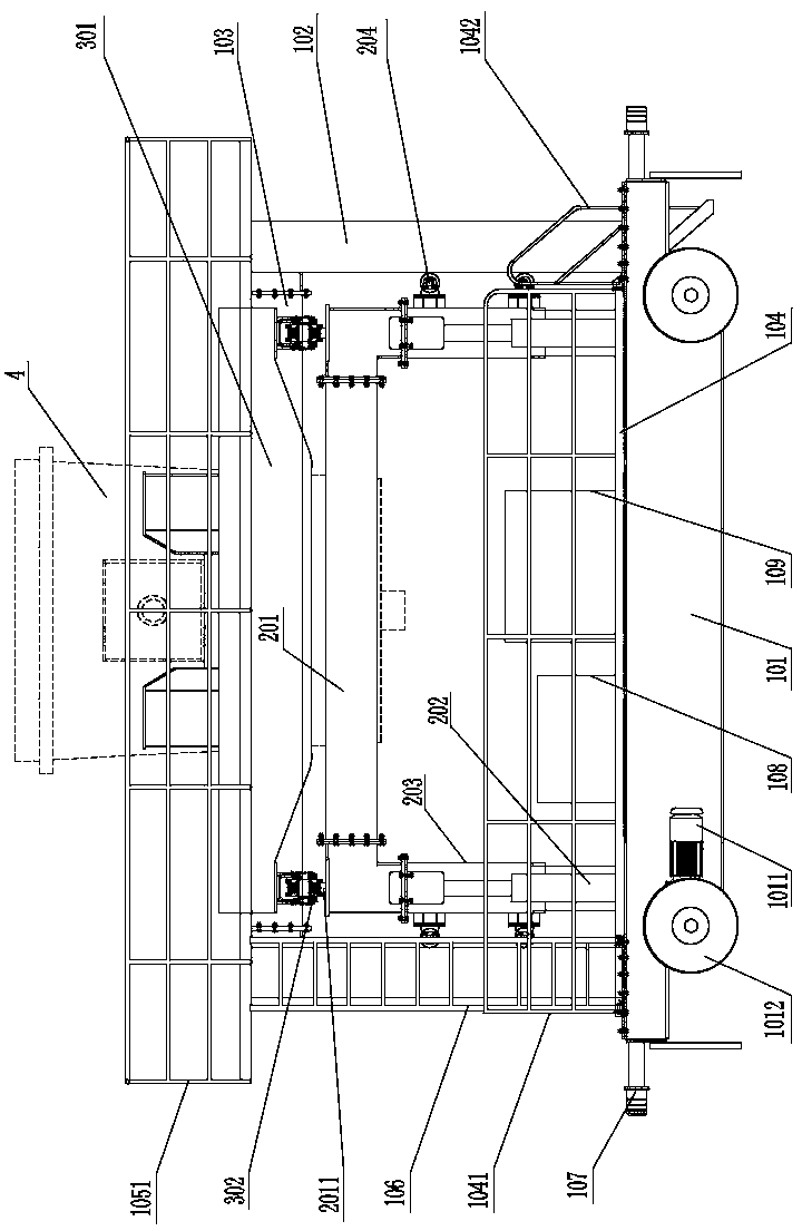
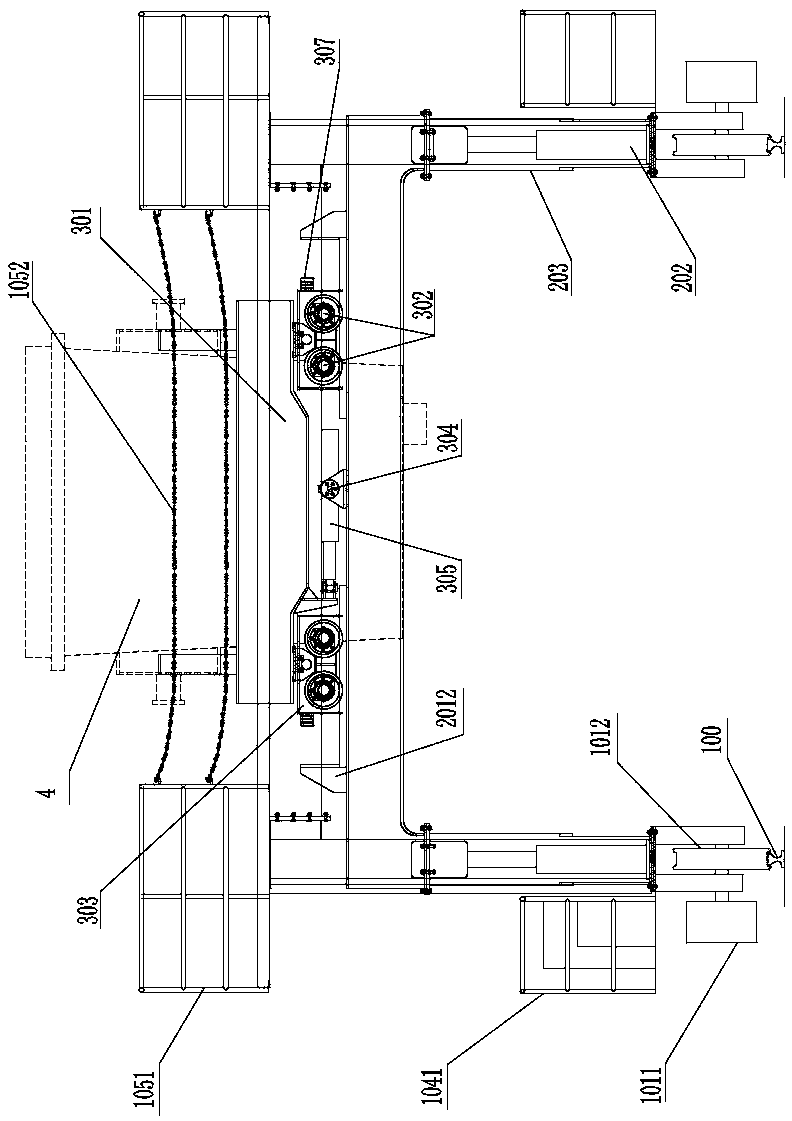
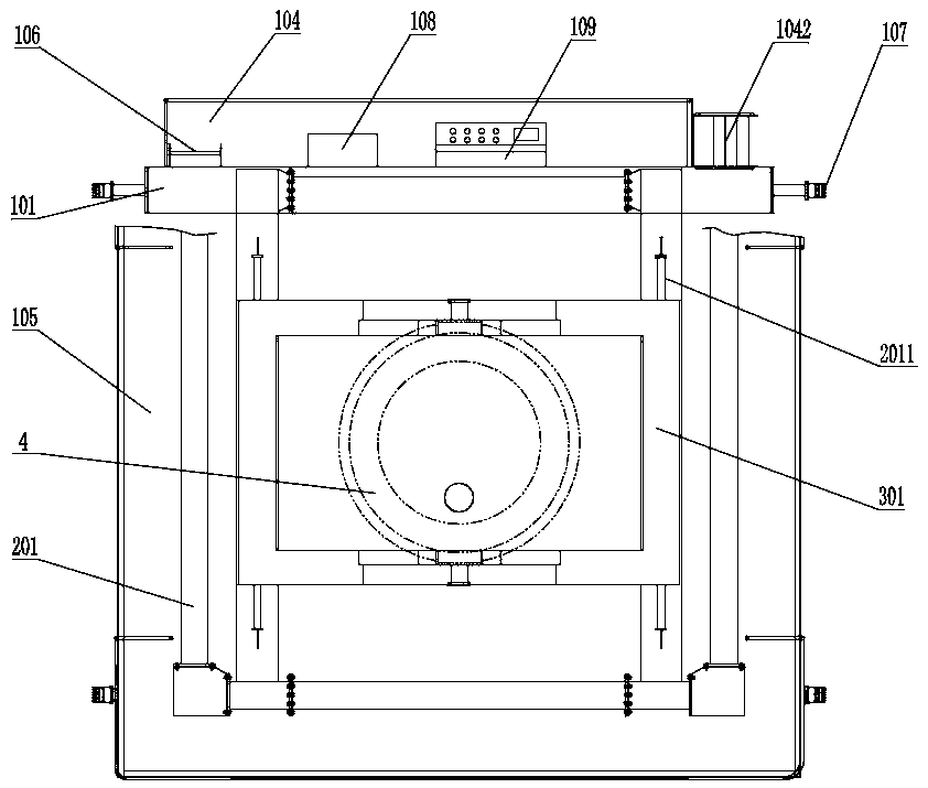
[0030] Such as Figure 1-Figure 4 As shown, the present invention provides a special hydraulic lifting and casting device for steel plant metallurgy, hereinafter referred to as the casting device, including a hydraulic pump station 108, a console 109, a cart operating mechanism, a lifting mechanism, a trolley operating mechanism and two parallel And the first track 100 that is arranged horizontally, the cart running mechanism includes two walking beams 101, the bottom of the walking beam 101 is rotatab...


PUM


Abstract

The invention discloses a hydraulic lifting casting device special for steel mill metallurgy. The device comprises a cart running mechanism, a hoisting mechanism, a trolley running mechanism and two first rails arranged in parallel; the cart running mechanism comprises two walking beams, the two walking beams are arranged on the first rails, the tops of the walking beams are fixedly connected withvertically-arranged supporting beams, and the tops of the supporting beams are fixedly connected with first cross beams; the hoisting mechanism comprises a hoisting frame of a rectangular structure,the hoisting frame is formed by connecting second cross beams end to end, second rails are arranged at the tops of the second cross beams, and first hydraulic cylinders are fixedly connected between the bottom of the hoisting frame and the tops of the walking beams; the trolley running mechanism comprises a steel ladle bracket, rollers are rotatably connected to the bottom of the steel ladle bracket and matched with the second rails, and the second cross beam is provided with a second hydraulic cylinder for driving the steel ladle bracket to move longitudinally; according to the invention, thesteel ladle can be stably, quickly and accurately moved, and the efficiency and safety of casting work are improved.

Description

technical field [0001] The invention relates to a casting device in the metallurgical industry, in particular to a special hydraulic lifting casting device for steel plant metallurgy. Background technique [0002] Casting is to inject the prepared casting raw material into the mold and let it solidify to obtain a product similar to the mold cavity. The casting raw material can be a monomer, a slurry that has been initially polymerized or polycondensed, or a solution of a polymer and a monomer. Wait. In the current metallurgical industry, the lifting device is used to control the movement of the ladle during the casting process. When the ladle moves to the casting port of the mold, the molten steel in the ladle is poured into the mold by manual operation. [0003] When the lifting device controls the movement of the ladle, the steel wire rope on the lifting device will shake, which will cause the ladle to shake, especially when the size and height of the mold are different a...

Claims


Application Information

Patent Timeline
Patent Type & Authority Applications(China)
IPC IPC(8): B66C19/00B66C13/06B66C13/12B66C9/14B66C5/02B66C7/16B22D41/12
CPCB66C19/00B66C13/06B66C13/12B66C9/14B66C5/02B66C7/16B22D41/12
Inventor 赵利娟
Owner HENAN BAOQI HUADONG CRANE
Learn More