Steel-concrete combined short-leg shear wall
A shear wall and concrete technology, applied in the direction of walls, formwork/formwork/work frame, building components, etc., can solve the problem of steel waste, reduce wet work, facilitate industrial production, and facilitate industrial production.
- Summary
- Abstract
- Description
- Claims
- Application Information
AI Technical Summary
Problems solved by technology
Method used
Image

Examples
Embodiment 1
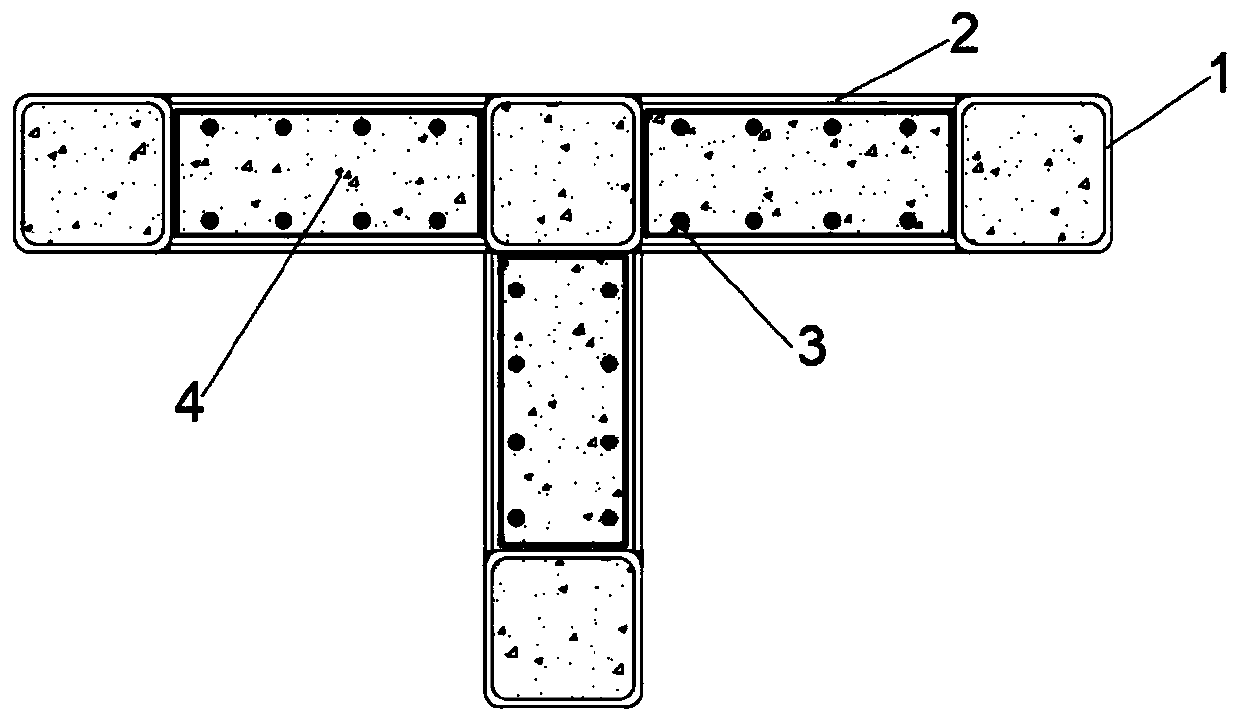
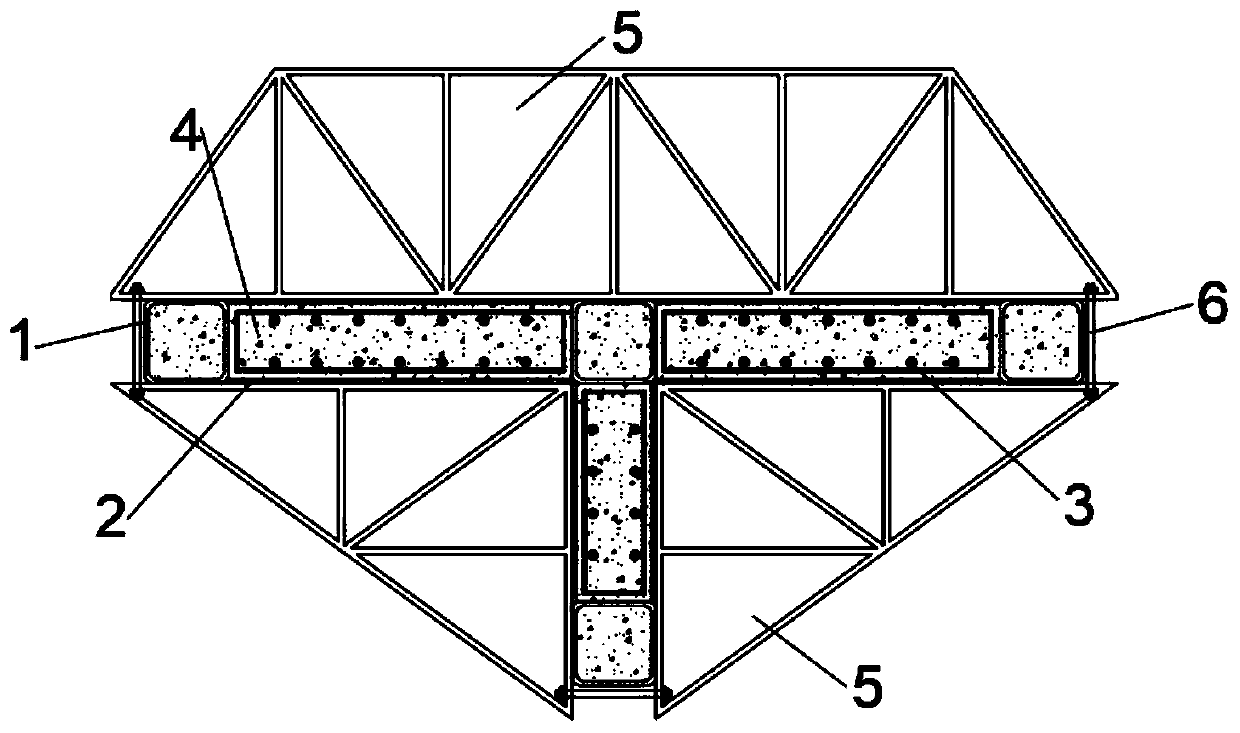
[0027] Such as figure 2 As shown, this embodiment takes the "T-shaped" short-leg shear wall as an example.
[0028] The T-shaped short-leg shear wall includes a square steel tube column 1, a steel plate 2, and a steel cage 3. Among them, the three ends of the short-leg shear wall and the middle corners are all equipped with steel pipe columns 1. The steel pipe columns 1 at the ends form end columns, and the steel pipe columns 1 at the middle corners form dark columns; six steel plates 2 Divided into three groups, each group includes two steel plates 2, respectively connecting the ends of the short-leg shear wall and the two steel pipe columns 1 at the corners; the steel plates 2 are arranged symmetrically, and the outer surface of the steel plate 2 is connected to the connected steel pipe column 1 The end faces of the steel plate are flush, and the steel plate 2 and the steel pipe column 1 are fixedly connected by welding. The welding process can be welded by industrial robots t...
Embodiment 2
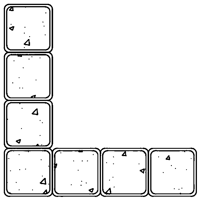
[0037] Such as Figure 4 As shown, this embodiment takes the "L-shaped" short-leg shear wall as an example.
[0038] The L-shaped short-leg shear wall includes a square steel tube column 1, a steel plate 2, and a steel cage 3. Among them, the two ends of the short-leg shear wall and the corners in the middle are equipped with steel pipe columns 1, the steel pipe columns 1 at the ends form end columns, and the steel pipe columns 1 at the middle corners form dark columns; four steel plates 2 Divided into two groups, each group includes two steel plates 2, respectively connecting the ends of the short-leg shear wall and the two steel pipe columns 1 at the corners; the steel plates 2 are arranged symmetrically, and the steel plates 2 are flush with the ends of the connected steel pipe columns 1 The steel plate 2 is connected to the steel pipe column 1 by welding. A pre-bound steel cage 3 is placed in the cavity formed between the steel plate 2 and the steel pipe column 1. The steel ...
Embodiment 3
[0045] Such as Image 6 As shown, this embodiment takes the "cross-shaped" short-leg shear wall as an example.
[0046] The cross-shaped short-leg shear wall includes a square steel tube column 1, a steel plate 2, and a steel cage 3. Among them, the four ends of the short-leg shear wall and the middle corners are equipped with steel pipe columns 1, the steel pipe columns 1 at the ends form end columns, and the steel pipe columns 1 at the middle corners form dark columns; eight steel plates 2 Divided into four groups, each group includes two steel plates 2, respectively connecting the ends of the short-leg shear wall and the two steel pipe columns 1 at the corners; the steel plates 2 are arranged symmetrically, and the steel plates 2 are flush with the two ends of the connected steel pipe columns , And the steel plate 2 and the steel pipe column 1 are fixedly connected by welding. The pre-bound steel cage 3 is placed in the cavity formed between the steel plate 2 and the steel pi...
PUM
 Abstract
Description
Claims
Application Information
 - R&D
- Intellectual Property
- Life Sciences
- Materials
- Tech Scout
- Unparalleled Data Quality
- Higher Quality Content
- 60% Fewer Hallucinations
Browse by: Latest US Patents, China's latest patents, Technical Efficacy Thesaurus, Application Domain, Technology Topic, Popular Technical Reports.
© 2025 PatSnap. All rights reserved.Legal|Privacy policy|Modern Slavery Act Transparency Statement|Sitemap|About US| Contact US: help@patsnap.com