Oil pumping unit semi-direct drive device

A driving device, semi-direct drive technology, applied in the direction of transmission, machine/engine, mechanical equipment, etc., can solve the problems of high maintenance cost, heavy maintenance workload, shutdown and replacement, etc., to achieve easy maintenance and avoid damage to the pumping unit , the effect of improving reliability

Active Publication Date: 2019-12-03
DAQING CITY HUAYU PETROLEUM MASCH MFG CO LTD
View PDF8 Cites 4 Cited by
  • Summary
  • Abstract
  • Description
  • Claims
  • Application Information

AI Technical Summary

Problems solved by technology

In the traditional beam pumping unit, the power output by the motor needs to pass through the belt transmission mechanism, the drive gear reducer and the connecting rod mechanism before it can be transmitted to the beam. There are two problems in this power transmission method: one is the transmission efficiency low, resulting in high energy consumption of the pumping unit; second, the belt in the belt drive mechanism is a vulnerable part, which needs to be shut down frequently for replacement, resulting in a large maintenance workload and high maintenance costs
[0003] In order to solve the above problems, the technicians developed the motor direct drive beam pumping unit with the original intention of improving the transmission efficiency and banning the belt drive mechanism. The performance puts forward higher requirements, which leads to a substantial increase in the cost of the motor and a substantial increase in the failure rate of the motor

Method used


Image

  • Oil pumping unit semi-direct drive device
  • Oil pumping unit semi-direct drive device
  • Oil pumping unit semi-direct drive device

Examples


Embodiment 1

[0037] The present invention will be further described below in conjunction with accompanying drawing:

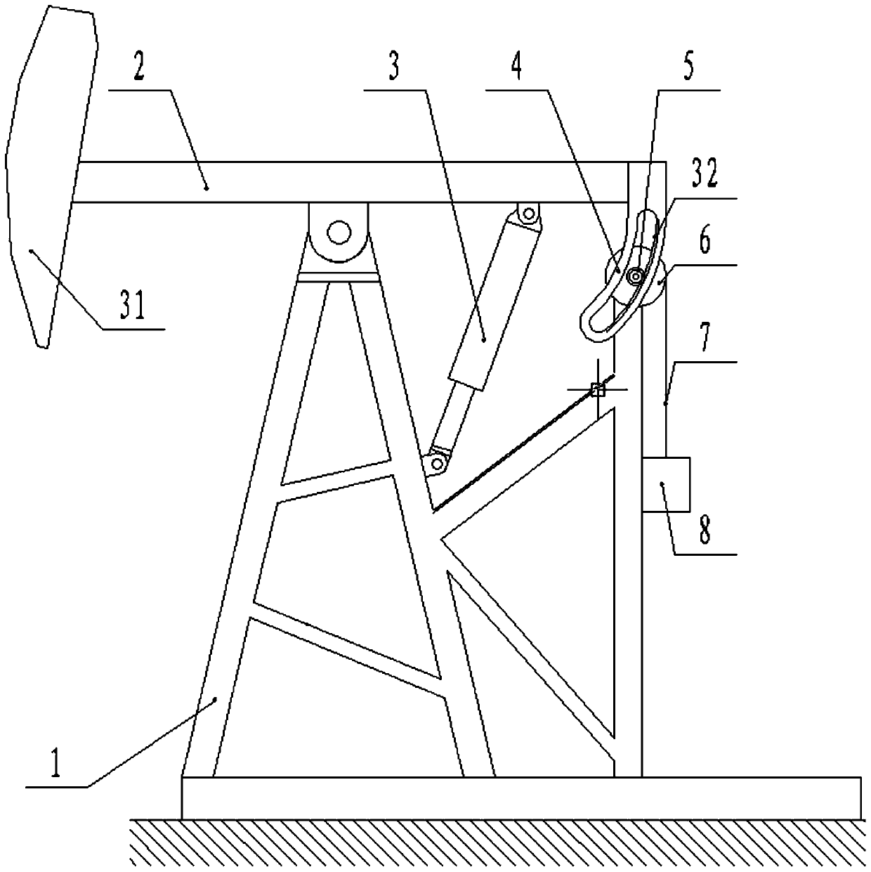
[0038] Such as figure 1 As shown, the present invention includes a support 1, a beam 2 and a driving mechanism 3, the middle part of the beam 2 is hinged on the top of the bracket 1, and the driving mechanism 3 is connected between the bracket 1 and the beam 2, and the above is a beam type oil pumping The basic structure of the machine will not be repeated here.

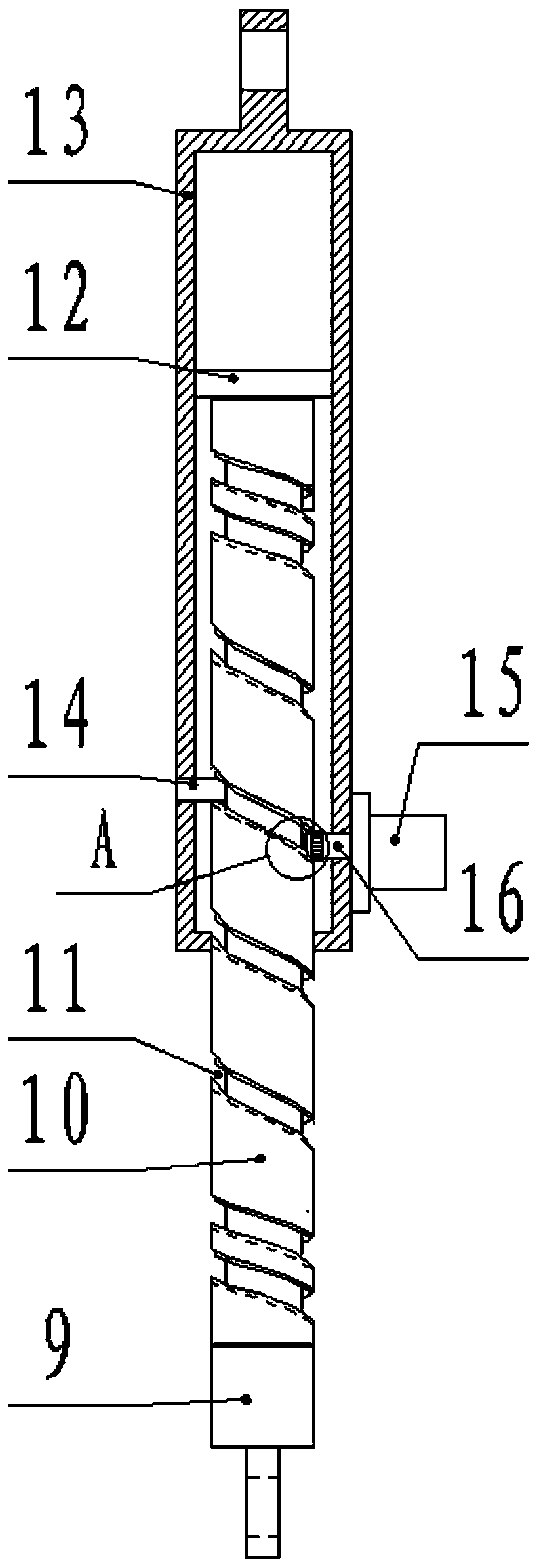
[0039] Such as figure 2 As shown, the driving mechanism 3 includes a cylinder A13, a screw shaft assembly and a motor 15. One end of the screw shaft assembly is inserted into the cylinder A13, the upper end of the cylinder A13 is hinged on the beam 2, and the lower end of the screw shaft assembly is hinged on bracket 1. During oil pumping, the drive mechanism 3 expands and contracts under the drive of the motor 15, so that the beam 2 swings to realize the oil pumping action.

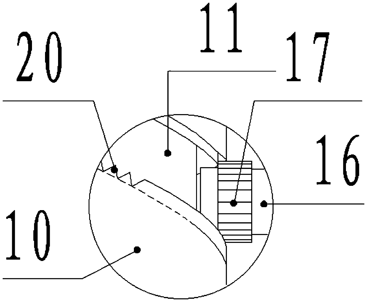
[0040] Such as Figure 6As show...

Embodiment 2

[0062] The difference between this embodiment and the first embodiment lies in the structure of the counterweight mechanism.

[0063] In this embodiment, the counterweight mechanism includes an arc guide rail 4, a follower gear 5, a wheel disc 6 and a counterweight 8. The arc guide rail 4 is fixedly connected to the bracket 1, and the center of the circle where the arc guide rail 4 is located is located on the beam. 2, an arc-shaped rack 32 is processed on the inner side of the arc-shaped guide rail 4, and the follower gear 5 is installed on the tail of the beam 2 through the gear shaft, and the follow-up gear 5 meshes with the arc-shaped rack 32 , the wheel disc 6 and the follower gear 5 are installed on the same shaft, so as to rotate synchronously with the follower gear 5 , the outer edge of the wheel disc 6 is provided with a rope groove, and a soft rope 7 is wound in the rope groove, and the soft rope 7 Hanging down from the edge of the wheel disc 6 along the tangential d...


PUM


Abstract

The invention belongs to the field of oilfield oil production equipment and in particular relates to an oil pumping unit semi-direct drive device. The oil pumping unit semi-direct drive device comprises a bracket, a walking beam and a driving mechanism; the middle part of the walking beam is hinged to the top end of the bracket; the driving mechanism is connected between the bracket and the walking beam; the driving mechanism comprises a cylinder body A, a spiral shaft component and a motor; one end of the spiral shaft component is inserted in the cylinder body A; the upper end of the cylinderbody A is hinged to the walking beam; the lower end of the spiral shaft component is hinged to the bracket; and a counterweight mechanism is arranged at the tail part of the walking beam. An energy storage device is connected to the driving mechanism. According to the oil pumping unit semi-direct drive device, an unprecedented spiral transmission mechanism is adopted to drive the walking beam toswing; compared with a traditional oil pumping unit, the oil pumping unit semi-direct drive device has the advantage that the oil pumping unit semi-direct drive device is easier to maintain due to abandoning a belt transmission mechanism; and compared with an existing motor direct-drive walking beam type oil pumping unit, the oil pumping unit semi-direct drive device has the advantages that requirements on parameters such as power, torque and starting performance of a motor are very low, and the motor operation reliability is also improved.

Description

technical field [0001] The invention belongs to the field of oil production equipment in oilfields, in particular to a semi-direct drive drive device for an oil pumping unit. Background technique [0002] The beam pumping unit is a commonly used oil extraction equipment. This pumping unit is powered by a motor to make the beam reciprocatingly swing to complete the oil pumping work. In the traditional beam pumping unit, the power output by the motor needs to pass through the belt transmission mechanism, the drive gear reducer and the connecting rod mechanism before it can be transmitted to the beam. There are two problems in this power transmission method: one is the transmission efficiency Low, resulting in high energy consumption of the pumping unit; Second, the belt in the belt drive mechanism is a vulnerable part, which needs to be shut down frequently for replacement, resulting in a large maintenance workload and high maintenance costs. [0003] In order to solve the ab...

Claims


Application Information

Patent Timeline
Patent Type & Authority Applications(China)
IPC IPC(8): E21B43/00F04B47/14F16H37/04
CPCE21B43/127F04B47/14F16H37/04
Inventor 徐海英
Owner DAQING CITY HUAYU PETROLEUM MASCH MFG CO LTD
Why Eureka
Try Eureka