Ventilation, dust removal and purification system

A purification system and cycle purification technology, which is applied in the field of ventilation, can solve the problems of high overall energy consumption, high system resistance, and high energy consumption of the refrigeration system, and achieve good ventilation and dust removal effects, reduced total energy consumption, and low system energy consumption.

Pending Publication Date: 2019-12-03
JIANGSU SANY ENVIRONMENTAL TECH LTD
View PDF8 Cites 5 Cited by
  • Summary
  • Abstract
  • Description
  • Claims
  • Application Information

AI Technical Summary

Problems solved by technology

[0004] 1. Blow-suction ventilation: air is supplied on one side of the column of the factory building, and exhaust is arranged on the other side of the column. Through the large-span air supply and exhaust, it tries to capture pollutants. Its characteristic is that the air supply is in the form of a jet. Due to the large span of the factory building, the jet angle is generally controlled within 10°, and the height required for the return air outlet is quite large. At the same time, the air flow in the workshop is disordered, and the personnel working area has not been treated, the pollution problem has not been fundamentally solved, and the energy consumption is high.
[0005] 2. Ventilation of the whole air system: Air distributors are arranged on both sides of the factory building, and return and exhaust outlets are set on the top to transport air and suck air through long distances. The system fan adopts a double fan system. The system resistance is as high as 3000Pa or more, and the fan energy consumption is high.
On the other hand, the system adopts a combined dust removal and temperature control unit. When the temperature and humidity need to be controlled, the full air volume needs to go through the surface cooler or evaporator to use low-temperature refrigerant for deep dehumidification, and the overall energy consumption of the refrigeration system is high.

Method used


Image

  • Ventilation, dust removal and purification system
  • Ventilation, dust removal and purification system
  • Ventilation, dust removal and purification system

Examples


no. 1 example

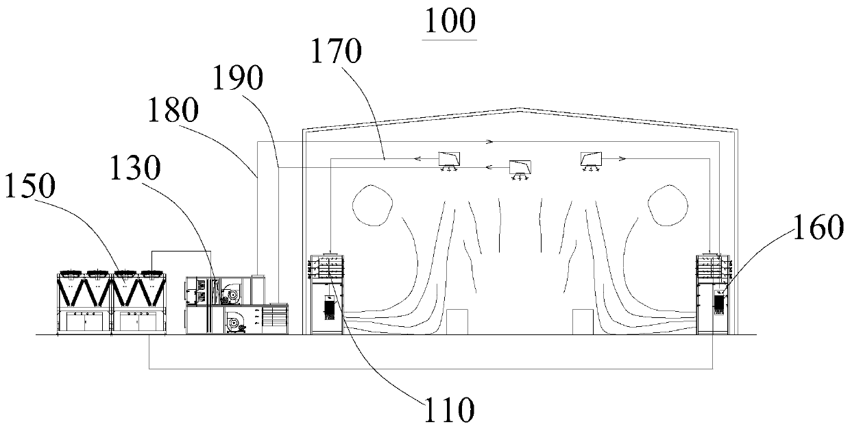
[0037] see in conjunction Figure 1 to Figure 3 , the present embodiment provides a ventilation, dust removal and purification system 100, which is mainly installed in the factory building 200, and plays the functions of ventilation, dust removal and purification of the air inside the factory building 200, and simultaneously controls the temperature and humidity inside the factory building 200 separately, Play the role of independent control of temperature and humidity.

[0038] The ventilation, dust removal and purification system 100 provided in this embodiment includes at least one circulation purification unit 110, at least one fresh air unit 130 and heat exchange unit 150, and the heat exchange unit 150 is respectively connected to the circulation purification unit 110 and the fresh air unit 130 for Exchange heat with the purification unit and the fresh air unit 130 respectively. The circulation purification unit 110 is arranged in the indoor space and is provided with a ...

no. 2 example

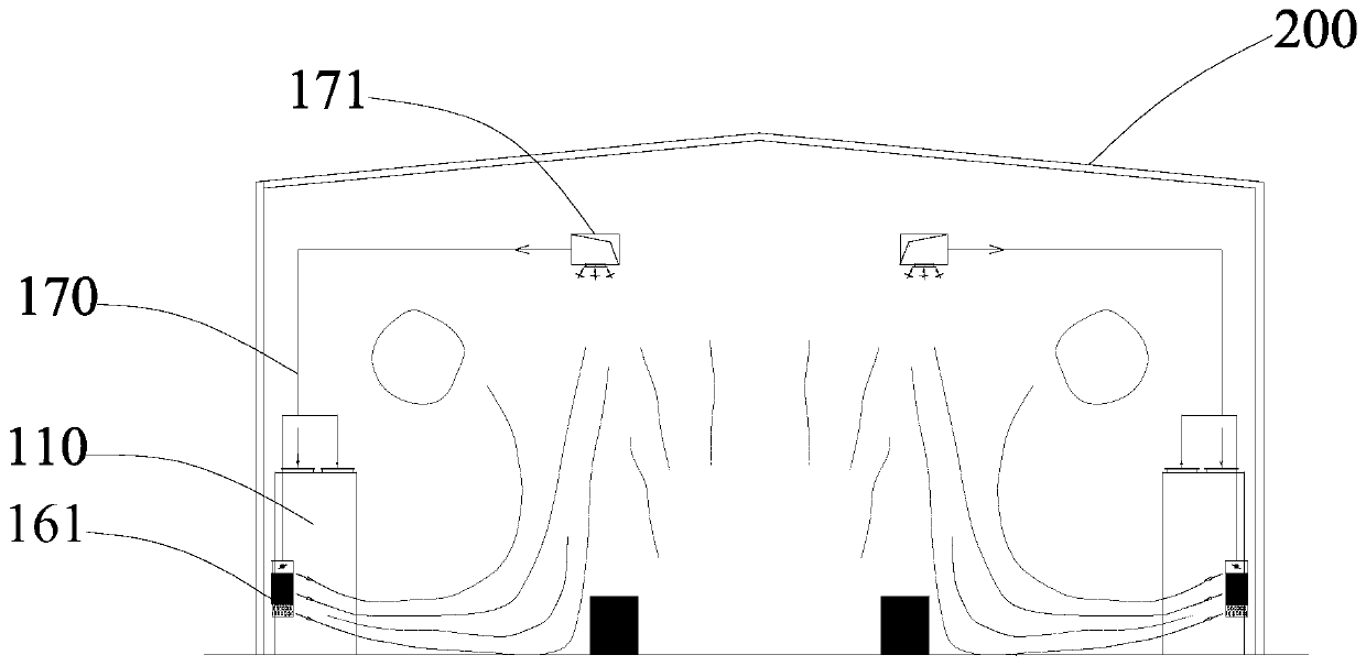
[0070] see in conjunction Figure 6 and Figure 7 , this embodiment provides a ventilation, dust removal and purification system 100, its basic structure and principle and the technical effects produced are the same as those of the first embodiment. corresponding content in the example. Compared with the first embodiment, the difference of this embodiment lies in the circulating purification unit 110 .

[0071] In this embodiment, the circulation purification unit 110 includes a circulation housing 111, a return air valve 113, a circulation purification assembly 115 and a static pressure air supply diffuser 119, the circulation housing 111 is arranged in the indoor space, and the return air valve 113 is arranged in the circulation One end of the housing 111 is connected to the air return pipe 170. The static pressure air diffuser 119 is arranged at the other end of the circulation housing 111 and has an air outlet. The circulation purification assembly 115 is accommodated in...

no. 3 example

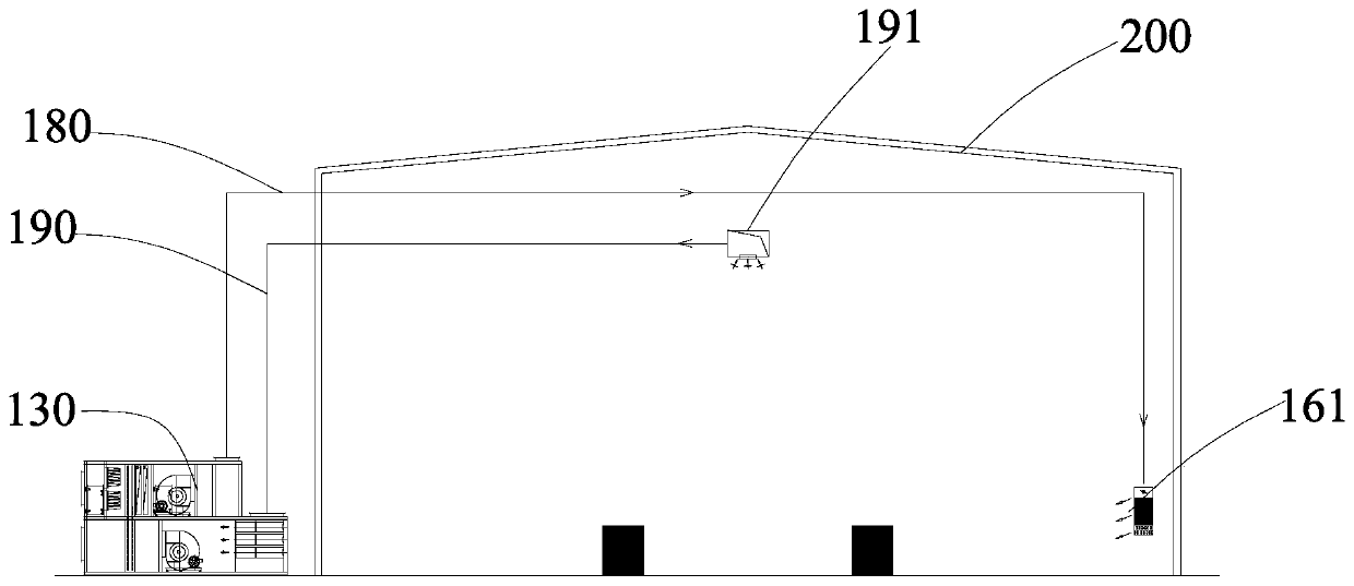
[0074] see Figure 8 , this embodiment provides a ventilation, dust removal and purification system 100, its basic structure and principle and the technical effects produced are the same as those of the second embodiment. corresponding content in the example. Compared with the second embodiment, the difference of this embodiment lies in the circulating purification unit 110 .

[0075] In this embodiment, the circulation purification unit 110 includes a circulation housing 111, a return air valve 113, a circulation purification assembly 115 and a static pressure air supply diffuser 119, the circulation housing 111 is arranged in the indoor space, and the return air valve 113 is arranged in the circulation One end of the housing 111 is connected to the air return pipe 170. The static pressure air diffuser 119 is arranged at the other end of the circulation housing 111 and has an air outlet. The circulation purification assembly 115 is accommodated in the circulation housing 111...


PUM


Abstract

The invention provides a ventilation, dust removal and purification system, and relates to the technical field of ventilation; the system comprises at least one circulating purification unit, at leastone fresh air unit and a heat exchange unit; the heat exchange unit is connected with the circulating purification unit and the fresh air unit, the circulating purification unit is arranged in an indoor space and provided with an air return pipe and an air outlet, and the air return pipe and the air outlet are both communicated with the indoor space and form indoor circulating purified airflow; the fresh air unit is arranged in the outdoor space and provided with a fresh air pipe and an exhaust pipe, and the fresh air pipe and the exhaust pipe both extend into the indoor space. Compared withthe prior art, the ventilation, dust removal and purification system provided by the invention is good in ventilation and dust removal effect, capable of purifying indoor air, low in system energy consumption, energy-saving and environment-friendly by separately arranging the fresh air pipe, the exhaust pipe and the air return pipe.

Description

technical field [0001] The invention relates to the technical field of ventilation, in particular to a ventilation dust removal and purification system. Background technique [0002] With the development of modern industrial technology, the construction of industrial plants in various industries is developing rapidly. The pollutants produced by industrial plants in the process of production are difficult to control. At the same time, there are strict requirements on temperature, humidity, pollutant concentration, noise, etc. At present All kinds of ventilation, dust removal, purification and air conditioning systems on the market have the characteristics of high energy consumption, especially for super large industrial plants, the energy consumption of the ventilation and dust removal, purification and air conditioning systems is quite large. [0003] At present, the airflow organization methods commonly used for ventilation and dust removal in industrial plants are as follo...

Claims


Application Information

Patent Timeline
Patent Type & Authority Applications(China)
IPC IPC(8): F24F7/08F24F3/14F24F3/16F24F12/00F24F13/24F24F13/28F24F13/30
CPCF24F3/14F24F7/08F24F12/002F24F13/24F24F13/28F24F13/30F24F2012/005F24F2013/242F24F8/10
Inventor 匡苍豪郑中平肖应龙欧建伏
Owner JIANGSU SANY ENVIRONMENTAL TECH LTD
Why Eureka
Try Eureka