Thin-layer chromatographic analyzer

A thin-layer chromatography and analyzer technology, applied in the field of thin-layer chromatography analyzers, can solve the problems of limited operator experience and accuracy in manual operation, affecting TLC analysis results, operator health hazards, etc., and reducing cumbersome high chromatographic quality, and the effect of reducing physical damage

Pending Publication Date: 2019-12-03
ANHUI UNIV OF SCI & TECH
View PDF0 Cites 0 Cited by
  • Summary
  • Abstract
  • Description
  • Claims
  • Application Information

AI Technical Summary

Problems solved by technology

[0005] 1. Manual operation is limited by the experience and accuracy of the operator, which will inevitably cause errors, and the entire operation process is in an open space, and the humidity and temperature of the environment will affect the results of TLC analysis
[0006] 2. Manual operation needs to be in close contact with the solvent, and the volatilization of some toxic and harmful solvents will cause harm to the health of the operator
[0007] 3. Most of the existing thin-layer chromatography analysis instruments (such as: automatic sample spotting instrument, automatic unfolding instrument, spray system, etc.) automate a certain step of the thin-layer chromatography analysis process, and the operator still needs to remove the carrier plate from the instrument. Take it out and place it in another instrument. This process is easily affected by the ambient temperature and humidity, resulting in poor chromatographic quality, and requires the operator to accompany the whole process, which is cumbersome and inefficient.

Method used


Image

  • Thin-layer chromatographic analyzer
  • Thin-layer chromatographic analyzer
  • Thin-layer chromatographic analyzer

Examples


Embodiment Construction

[0032] The technical solutions in the present invention will be clearly and completely described below in conjunction with the accompanying drawings in the embodiments of the present invention. Obviously, the described embodiments are only some, not all, embodiments of the present invention. Based on the embodiments of the present invention, all the embodiments obtained by persons of ordinary skill in the art without making creative efforts belong to the protection scope of the present invention.

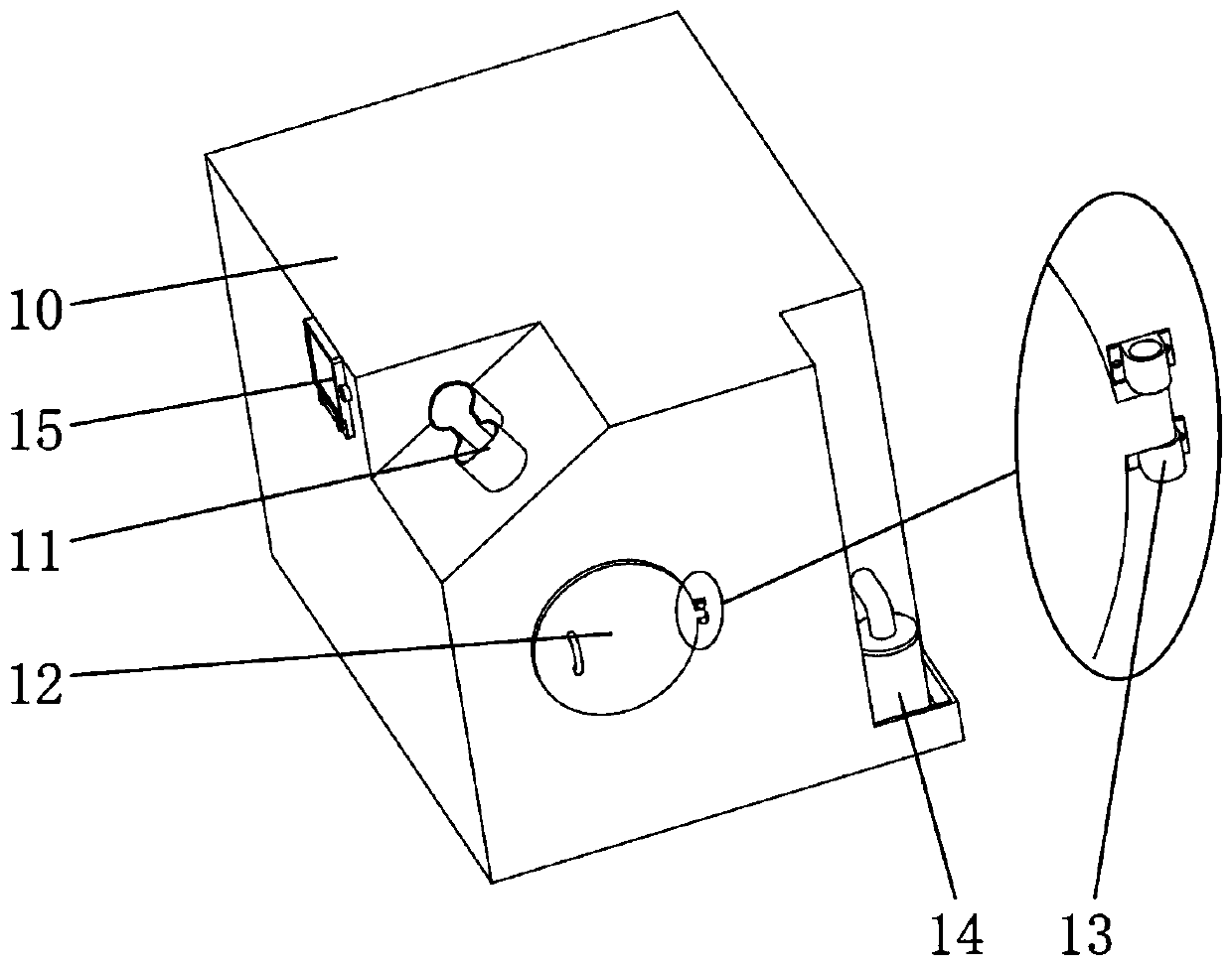
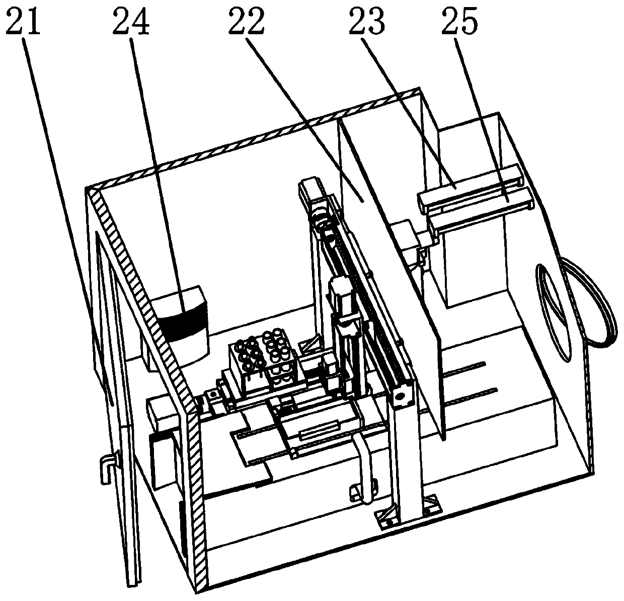
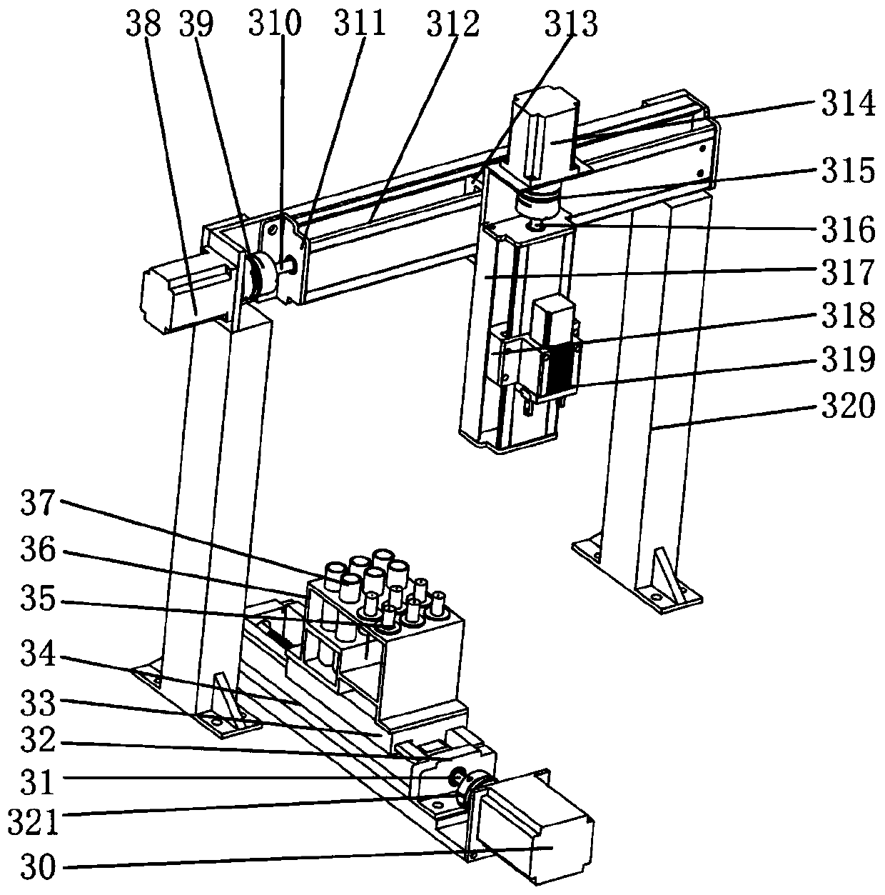
[0033] see Figure 1 to Figure 10, a technical solution provided by the present invention: comprising a constant temperature box, a fixed frame, a pillar and a diaphragm pump, characterized in that: a fixed support is fixed on the right side surface of the constant temperature box, and the fixed support is hinged to the right side door, A sealed door is hinged on the left side of the incubator, a partition is arranged inside the incubator, a humidifier is fixed inside the incubator,...


PUM


Abstract

The invention discloses a thin-layer chromatographic analyzer which highly integrates functions of sample application, drying, unfolding, color development and the like. The analyzer mainly comprisesa constant-temperature box, a fixing frame, a test tube rack, a support column and a diaphragm pump. An ultraviolet lamp and an incandescent lamp are fixedly mounted at the top of the constant-temperature box and the bottom of the constant-temperature box is fixedly connected with the fixing frame. A hot-air blower is fixed at the bottom of the fixing frame through a fan support base. The test tube rack is fixedly mounted on a sliding table 1; a capillary tube and a test tube are arranged on the test tube rack. The support column is fixed in the constant-temperature box; a sliding table set isinstalled on the support column; and an electric clamping jaw is installed on the sliding table 3 and is used for clamping the capillary tube. The diaphragm pump is fixedly installed on the inner wall of the constant-temperature box; one end is in sealed connection with a water suction pipe to suck a color developing agent from a color developing agent cup; and the other end is in sealed connection with a water outlet pipe to evenly spray the color developing agent in a mist spray manner from the water outlet pipe. The analyzer has advantages of small size, simplicity and convenience in operation, high efficiency, high safety and the like.

Description

technical field [0001] The invention relates to the technical field of medical instruments, in particular to a thin-layer chromatography analyzer. Background technique [0002] Thin-layer chromatography is a commonly used trace and rapid chromatography. It has the advantages of less time-consuming, high sensitivity, and convenient operation, so it is widely used in chemical, pharmaceutical and other fields. Its main working principle is to evenly coat the adsorbent into a thin layer on the carrier plate (glass plate, plastic plate, etc., which has a certain strength and chemical inertness), and then absorb the sample solution through the capillary and accurately place it on the load at a distance. On a straight line 1-2 cm from one end of the board. After the solvent evaporates, put the carrier plate into the pre-saturated developing cylinder. Due to capillary action, the sample solution slowly advances on the thin-layer plate. After advancing to a certain distance, take ou...

Claims


Application Information

Patent Timeline
Patent Type & Authority Applications(China)
IPC IPC(8): G01N30/90G01N30/94
CPCG01N30/90G01N30/94
Inventor 田晔胡聪孙瑶瑶王雷陈星鲍帅邓海顺
Owner ANHUI UNIV OF SCI & TECH
Why Eureka
Try Eureka