Time-delay switch driving circuit and system

A delay circuit and switching circuit technology, applied in the direction of electrical components, output power conversion devices, etc., can solve the problems of the system not starting normally, incomplete discharge, affecting the performance of the electronic equipment system, etc., to achieve high mass production and cost advantages, filtering jitter, and avoiding the effect of crossover loss

Pending Publication Date: 2019-12-03
重庆市亿飞智联科技有限公司
View PDF0 Cites 4 Cited by
  • Summary
  • Abstract
  • Description
  • Claims
  • Application Information

AI Technical Summary

Problems solved by technology

[0005] The purpose of the present invention is to provide a time-delay switch drive circuit and system in view of the deficiencies in the above-mentioned prior art, so as to solve the electronic system existing in the prior art during the power-off and restart process, which uses power-on immediately after power-off. , the load in the system is not completely discharged before the second power-on, which leads to the failure of the system to start normally and affects the performance of the electronic equipment system

Method used


Image

  • Time-delay switch driving circuit and system
  • Time-delay switch driving circuit and system
  • Time-delay switch driving circuit and system

Examples


Embodiment Construction

[0042] In order to make the purpose, technical solutions and advantages of the embodiments of the present invention clearer, the technical solutions in the embodiments of the present invention will be clearly and completely described below in conjunction with the drawings in the embodiments of the present invention. Obviously, the described embodiments It is a part of embodiments of the present invention, but not all embodiments.

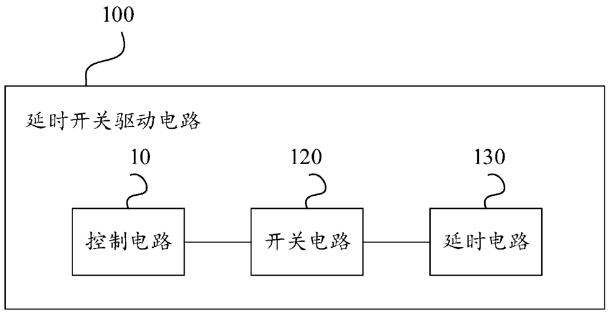
[0043] figure 1 A schematic structural diagram of a time-delay switch drive circuit provided for the embodiment of the present application; figure 1 As shown, the delay switch drive circuit 100 includes: a control circuit 10, a switch circuit 120 and a delay circuit 130; wherein, the input terminal of the control circuit 10 is electrically connected to the power-off restart control pin, and the output terminal of the control circuit 10 It is electrically connected to the input end of the switch circuit 120, the output end of the switch circuit 120 ...


PUM


Abstract

The invention provides a time-delay switch driving circuit and system and relates to the technical field of switch control driving circuits. The circuit comprises a control circuit, a switch circuit and a time delay circuit, wherein the control circuit, the switch circuit and the time delay circuit are electrically connected in sequence, an input end of the control circuit is electrically connected with a power-off control pin, an output end of the time delay circuit is connected with a controlled switch power supply, the control circuit controls the switch circuit and the time delay circuit to be disconnected or connected through a level signal outputted by the power-off control pin in an enabled state or an unenabled state, so the time delay circuit outputs a power-off signal or a restart signal to the controlled switch power supply to control the controlled switch power supply for being disconnected and automatically restarted, moreover, through the time delay circuit, the controlled switch power supply can be powered off or restarted after the power-off control pin outputs the level for a preset time, and thereby a capacitive load in an electronic equipment system can be completely discharged before restarting, and damage to the controlled switch power supply is avoided.

Description

technical field [0001] The invention relates to the technical field of switch control drive circuits, in particular to a delay switch drive circuit and system. Background technique [0002] With the continuous advancement and development of science and technology, people's lives are inseparable from electronic devices. During the use of electronic devices, when encountering situations such as machine jams or resource updates, it is inevitable that the electronic device system needs to be restarted. Ensure the normal operation of electronic equipment. [0003] In the existing electronic equipment system, when the system is powered off and restarted, the method of powering on and starting immediately after the system is powered off is often adopted. [0004] However, the complexity of the internal structure of the electronic equipment system is different. If the power is turned on immediately after the power is turned off, the system will be powered on again if the discharge ...

Claims


Application Information

Patent Timeline
Patent Type & Authority Applications(China)
IPC IPC(8): H02M1/36
CPCH02M1/36
Inventor 韩长久谢云
Owner 重庆市亿飞智联科技有限公司
Why Eureka
Try Eureka