Phase change cooling system

A cooling system and phase change cooling technology, applied in the field of electronics, can solve the problems of pressure and temperature fluctuation, difficulty in heat dissipation and temperature control, and difficulty in accurate control of system temperature, so as to alleviate pressure rise and fluctuation and improve condensation heat transfer. Efficiency and the effect of ensuring stable operation

Inactive Publication Date: 2019-12-03
CHINA AVIATION OPTICAL-ELECTRICAL TECH CO LTD
View PDF3 Cites 8 Cited by
  • Summary
  • Abstract
  • Description
  • Claims
  • Application Information

AI Technical Summary

Problems solved by technology

[0003] The traditional air-cooled and liquid-cooled heat dissipation methods cannot solve the heat dissipation problem of high heat flux density electronic devices, and the traditional liquid-cooled heat dissipation scheme uses a cooling medium that is mostly conductive. If it leaks, it will cause equipment damage and pose a safety hazard; especially for long-distance distributed , It is very difficult to dissipate heat and control the temperature of the uneven heat source. The existing pump-driven two-phase cooling system will have large pressure and temperature fluctuations, especially when the scale of the system is relatively large, caused by changes in the high and low temperature of the system The volume of the working medium in the liquid storage tank changes greatly, and the liquid level fluctuates continuously, which brings difficulties to the accurate control of the system temperature

Method used


Image

  • Phase change cooling system

Examples


Embodiment Construction

[0015] The present invention can be explained in detail through the following examples, and the purpose of disclosing the present invention is to protect all technical improvements within the scope of the present invention.

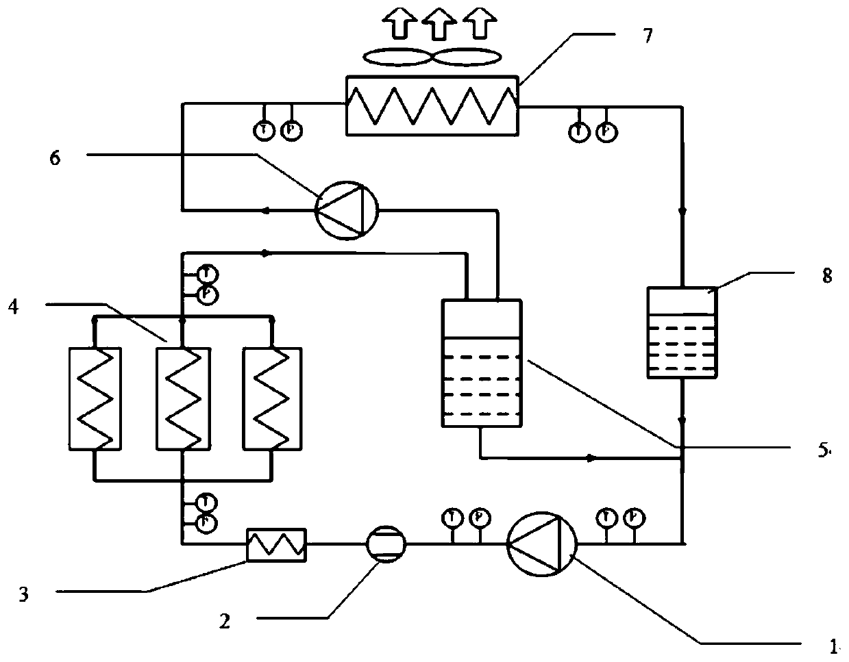
[0016] The pump-driven two-phase cooling system is mainly composed of a liquid pump 1, an evaporator 4, a condenser 7, a preheater 3, a vapor-liquid separator 5, a liquid storage tank 8, a gas pump 6, and connecting pipelines. To achieve liquid phase conversion heat, accurate temperature control, and safe and stable operation, temperature and pressure sensors are installed at the inlet and outlet of evaporator 4, condenser 7, and liquid pump 1 to monitor the operating pressure and temperature of the system. The schematic diagram of the principle is as follows figure 1 shown.

[0017] Driven by the pump, the liquid working medium enters the preheater 3 to be preheated to a nearly saturated state, and then enters the flow channel of the evaporator 4 to be h...


PUM


Abstract

The invention discloses a phase change cooling system. The system comprises a liquid pump, a flow meter, an evaporator, a condenser, a preheater, a vapor-liquid separator, a liquid storage tank, a gaspump and a connecting pipeline. The system provided by the invention has the advantages that the vapor-liquid separator and the liquid storage tank are arranged in the system, reducing pressure pulses during the startup process of the system and improving the operation stability of the system; the gas pump arranged in the system can quickly separate vapor and liquid of a vapor-liquid two-phase working fluid flowing from the evaporator through the vapor-liquid separator, and then suck the working fluid into the condenser to condense and release heat; the condensation heat transfer efficiency can be improved; pressure rise and fluctuation caused by boiling heat transfer in the system are alleviated; and stable operation of the system is ensured.

Description

technical field [0001] The invention belongs to equipment cooling technology in the electronic field, and in particular relates to a phase change cooling system. Background technique [0002] With the development of technology, although electronic equipment has been continuously improved in terms of materials and performance, it is still becoming more and more difficult to control the heat dissipation and temperature of high-power, high-throughput electronic equipment. The cooling limit of conventional air-cooled and liquid-cooled cooling methods is only 100W / cm 2 , while the heat of electronic components often exceeds 100W / cm 2 , even up to 200W / cm 2 . [0003] The traditional air-cooled and liquid-cooled heat dissipation methods cannot solve the heat dissipation problem of high heat flux density electronic devices, and the traditional liquid-cooled heat dissipation scheme uses a cooling medium that is mostly conductive. If it leaks, it will cause equipment damage and po...

Claims


Application Information

Patent Timeline
Patent Type & Authority Applications(China)
IPC IPC(8): H05K7/20
CPCH05K7/2029
Inventor 蔡艳召黄胜利高长松冯亚利魏鹏
Owner CHINA AVIATION OPTICAL-ELECTRICAL TECH CO LTD
Why Eureka
Try Eureka