Mold and bottom pressure grouting system for gel casting ceramic slice

A technology of injection molding and ceramic flakes, which is applied in the direction of die-casting molds, ceramic molding machines, manufacturing tools, etc., to achieve good sealing, avoid air bubbles, improve the speed and uniformity of grouting

Inactive Publication Date: 2019-12-06
SHANDONG RES & DESIGN ACADEMY OF IND CERAMICS
View PDF0 Cites 1 Cited by
  • Summary
  • Abstract
  • Description
  • Claims
  • Application Information

AI Technical Summary

Problems solved by technology

[0003] In order to solve the above technical problems, the embodiment of the present invention proposes a mold and a bottom pressure grouting system for gel-casting ceramic sheets, which solves the problems of mold sealing and adjacent gaps caused by injecting ceramic slurry from the bottom in the prior art. Communication problem between cavities

Method used


Image

  • Mold and bottom pressure grouting system for gel casting ceramic slice
  • Mold and bottom pressure grouting system for gel casting ceramic slice

Examples


Embodiment 1

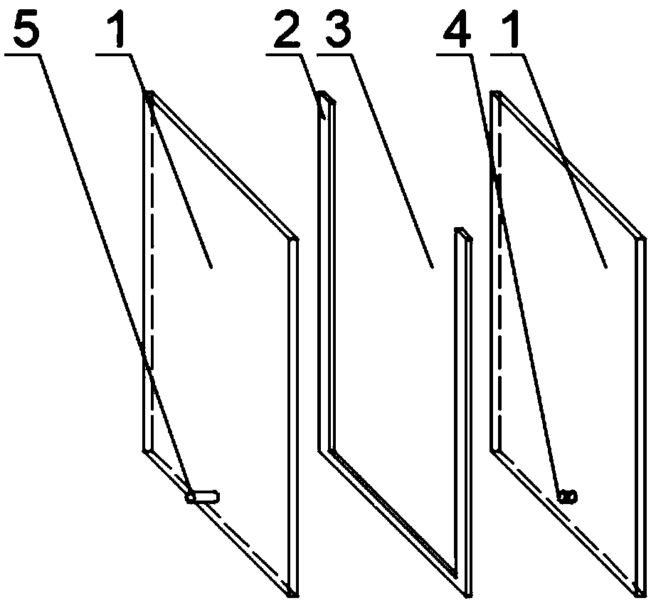
[0024] The present invention claims to protect a mold for gel-casting ceramic sheets, which includes partitions 1, gaskets 2 are arranged between adjacent partitions 1, the gaskets 2 are U-shaped, and the adjacent partitions A grouting mold cavity 3 is set between the plate 1 and the U-shaped gasket 2, and the partition 1 is sealed with the bottom of the gasket 2 and the bottom of the grouting mold cavity 3. The grouting channel 4 of the cavity 3 communicates with the grouting port 5 provided on the partition 1 .

[0025] Preferably: the material of the separator is glass.

[0026] Preferably: the separator 1 is square. Further, the width of the U-shaped spacer 2 is the same as that of the square.

[0027] In the prior art, the method of injecting slurry from the top of the gel-casting-shaped ceramic sheet will generate a large number of air bubbles, so that there are many defects in the formed ceramic green sheet, especially for the green sheet with a thickness of less than...

Embodiment 2

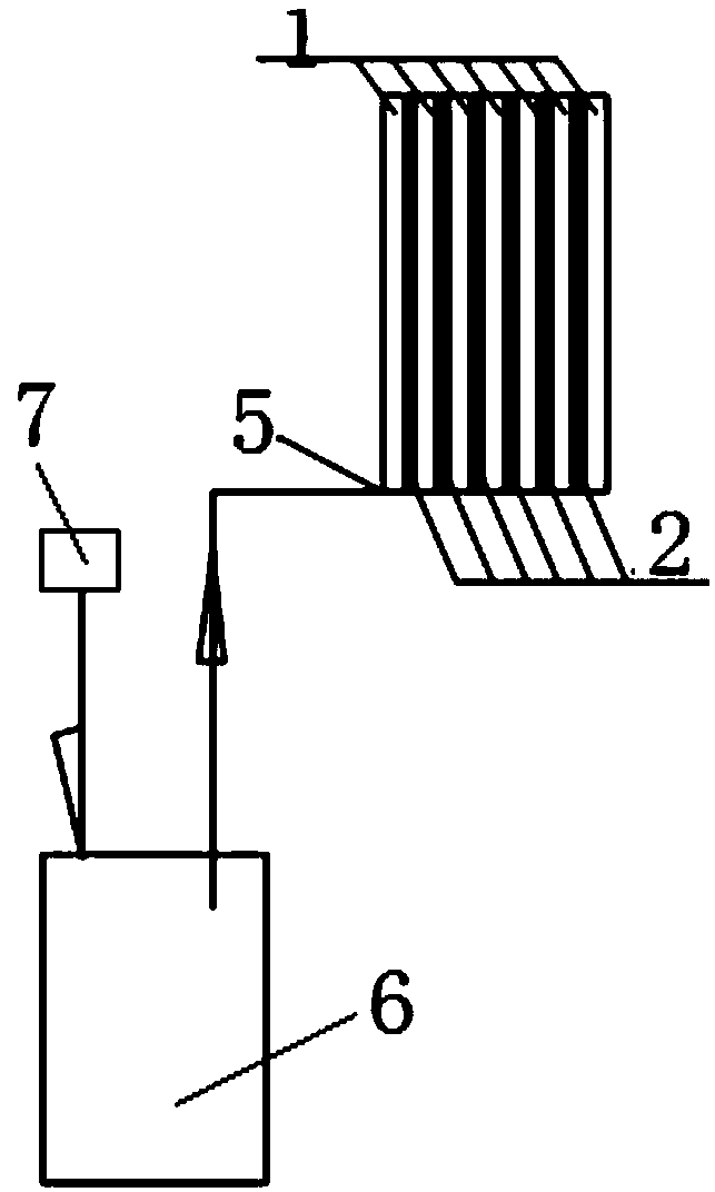
[0029] The features of this embodiment that are the same as those of Embodiment 1 will not be repeated here. The difference between this embodiment and the above embodiments is that the number of the grouting port 5 is one, and the shape of the grouting port 5 is circular.

[0030] The circular grouting port 5 is conveniently connected with the pipeline from the slurry tank 6 in a sealed manner, which improves the sealing performance of the mould.

Embodiment 3

[0032] The characteristics of this embodiment that are the same as those of Embodiment 1 or Embodiment 2 will not be repeated here. The difference between this embodiment and the above embodiments is that the grouting channel 4 is parallel to the bottom surface of the mould.

[0033] Preferably: the grouting channel 4 is located at the same height as the mold, and the height of the spacer 2 is smaller than that of the partition.

[0034] Preferably: the U-shaped gasket 2 is also provided with a grouting channel 4 .

[0035] The setting of these technical features improves the flow velocity of the slurry in different grouting channels 4 and mold cavities, and improves the efficiency of grouting.


PUM


Abstract

The invention discloses a mold and bottom pressure grouting system for a gel casting ceramic slice. The mold comprises partition plates, a gasket is arranged between every two adjacent partition plates, each gasket is in a U shape, a grouting mold cavity is formed among every two adjacent partition plates and the corresponding U-shaped gasket, the partition plates and the bottoms of the gaskets and the bottoms of the grouting mold cavities are sealed, a grouting channel communicating with the corresponding grouting mold cavity is arranged in one of the adjacent partition plates, and each grouting channel communicates with a grouting port arranged on the other one of the adjacent partition plates. According to the mold for the gel casting ceramic slice, grouting is directly conducted from the interiors of the partition plates and the interiors or the upper portions of the U-shaped gaskets, the problem that the bottom of the mold is leaked can not occur, the sealing property of the wholemold is good, communication between the interior and the exterior of the mold is improved through the U-shaped gaskets, the grouting rate and the grouting uniformity can be improved, and generation of bubbles is avoided.

Description

technical field [0001] The invention relates to the technical field of gel-casting molding of ceramic sheets, in particular to a mold and a bottom pressure grouting system for gel-casting ceramic sheets. Background technique [0002] The traditional method of using gel casting technology to form ceramic sheets is to inject slurry from the top of the mold into the cavity, and the slurry flows naturally from top to bottom inside the cavity, gradually filling the cavity. In the grouting method, a large number of air bubbles will be generated during the flow of the slurry, so that there are many defects in the formed ceramic green sheet. Especially for blanks with a thickness of less than 0.6mm, due to the viscosity of the slurry, the fluidity is poor, and it is difficult to flow in a small gap. The traditional grouting method basically cannot meet the forming of the blanks. Contents of the invention [0003] In order to solve the above technical problems, the embodiment of t...

Claims


Application Information

Patent Timeline
IPC IPC(8): B28B1/26
CPCB28B1/261B28B1/265
Inventor 吕锋赵小玻王玉宝张永翠鲍晓芸孝本周徐先豹
Owner SHANDONG RES & DESIGN ACADEMY OF IND CERAMICS
Why Eureka
Try Eureka