Connection joint of prefabricated floor slab and beam

A connection node and prefabricated technology, applied in building components, building thermal insulation materials, buildings, etc., can solve the problems of difficult to adapt to the rapid construction of light-weight housing structure floor slabs, no insulation and sound insulation, air purification and waterproofing, and complex connection methods. To achieve the effect of shortening the construction period, good waterproofness, and reducing waste

Pending Publication Date: 2019-12-06
SHENYANG JIANZHU UNIVERSITY
0 Cites 2 Cited by

AI-Extracted Technical Summary

Problems solved by technology

Aiming at the existing prefabricated floor slabs in the related art have complex connection methods, slow construction speed, difficulty in adapting to the rapid constructi...

Method used

Embodiment: as shown in Fig. 1-Fig. 5, a kind of connection node of prefabricated floor slab and beam, comprises first floor slab 1, second floor slab 2, beam 3, reserved bolt hole 4, high-strength bolt 5, Cast-in-situ concrete 6, water-expanding agent 7, the first floor 1 side is prefabricated with the first floor extended rib 1-1 outward, and the first floor extended rib 1-2 is reserved at the lower part of the same side, and the first floor There are reserved bolt holes 4 inside the protruding ribs of the first floor; the protruding ribs 2-1 of the second floor are prefabricated on one side of the second floor 2 outwards, and the protruding ribs 2-2 of the second floor are reserved at the lower part of the same side. There are reserved bolt holes 4 inside the protruding ribs 2-1 of the second floor; the upper part of the beam 3 is prefabricated outwards and the protruding rectangular ribs 3-1 are r...

Abstract

The invention provides a connection joint of a prefabricated floor slab and a beam. The connection joint comprises a first floor slab, a second floor slab, the beam, reserved bolt holes, high-strengthbolts, cast-in-situ concrete, a water swelling agent and the like. The connection joint is connected with a toe slab by insertion of a buttress T-shaped rib into a toe slab T-shaped groove to form abuttress retaining wall unit. The floor slab is formed integrally by the first floor slab and the second floor slab which are in lap joint by a first floor slab extension rib and a second floor slab extension rib; the floor slab is lapped at the upper part of a rectangular extension rib of the beam; the first floor slab extension rib and the second floor slab extension rib are integrally connectedwith the beam by a built-in reserved steel bar channel of the beam; the water swelling agent is added to the joint between the first floor slab and the second floor slab. The connection joint has theadvantages of good connection integrity of joints between the floor slab and the wall, shortened construction period, convenience in construction and transportation, high construction speed, reducedwaste, simple structure and the like, and greatly improves construction efficiency.

Application Domain

Technology Topic

Image

  • Connection joint of prefabricated floor slab and beam
  • Connection joint of prefabricated floor slab and beam
  • Connection joint of prefabricated floor slab and beam

Examples

  • Experimental program(1)

Example Embodiment

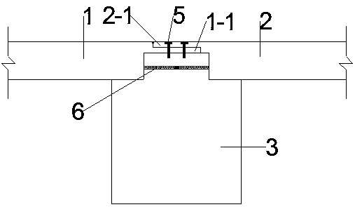
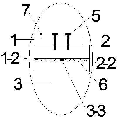
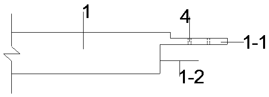
[0018] Example: such as Figure 1-Figure 5 As shown, a prefabricated floor and beam connection node includes the first floor 1, the second floor 2, the beam 3, the reserved bolt holes 4, the high-strength bolts 5, the cast-in-place concrete 6, and the water expansive agent 7. The first floor extension rib 1-1 is prefabricated on one side of the first floor slab 1, and the first floor extension rib 1-2 is reserved at the lower part of the same side, and the first floor extension rib has reserved bolt holes 4 inside. ; The second floor 2 side outward prefabricated second floor extension rib 2-1, the lower part of the same side reserved second floor extension rib 2-2, the second floor extension rib 2-1 inside Reserve bolt holes 4; the upper part of the beam 3 is prefabricated outwardly extending rectangular ribs 3-1, internal reserved steel channels 3-2, and built-in steel reinforcement sleeves 3 are prefabricated inside the internal reserved steel channels 3-2 -3; The first floor extension rib 1-1 and the second floor extension rib 2-1 are overlapped on the upper part of the extension rectangular rib 3-1, and the floor and the beam 3 are connected as a whole through the high-strength bolt 5; The first floor slab extension bar 1-2 and the second floor slab extension bar 2-2 are connected through the built-in reserved steel channel 3-2, and are connected by the built-in steel sleeve 3-3. After the connection is completed, the built-in steel channel 3- 2 Fill the cast-in-place concrete 6 to connect the first floor 1, the second floor 2 and the beam 3 into a whole; after the connection of the floor slab is completed, the first floor slab extension rib 1-1 is connected with the second floor slab extension rib 2-1 Add water swelling agent 7 everywhere to play a good waterproof effect.
[0019] The first floor extension rib 1-1 and the first floor extension rib 1-2 on the first floor 1 and the second floor extension rib 2-1 and the second floor extension rib 2-1 on the second floor 2 The positions of 2-2 correspond; the reserved bolt holes 4 on the first floor 1 and the second floor 2 correspond to the positions of the reserved bolt holes 4 of the extending rectangular rib 3-3.
[0020] The first floor slab extension rib 1-2 and the second floor slab extension rib 2-2 correspond to the positions of the built-in reserved steel channel 3-2. The two ends of the built-in steel reinforcement sleeve 3-3 are respectively connected with the first external reinforcement 1-2 and the second floor extension reinforcement 2-2 through threads. The size of the built-in steel reinforcement sleeve 3-3 is the same as that of the first external reinforcement 1 -2 has the same size as the second floor extension rib 2-2, which can connect the steel bars.

PUM

no PUM

Description & Claims & Application Information

We can also present the details of the Description, Claims and Application information to help users get a comprehensive understanding of the technical details of the patent, such as background art, summary of invention, brief description of drawings, description of embodiments, and other original content. On the other hand, users can also determine the specific scope of protection of the technology through the list of claims; as well as understand the changes in the life cycle of the technology with the presentation of the patent timeline. Login to view more.

Similar technology patents

Classification and recommendation of technical efficacy words

  • Overall good
  • Good waterproof

Production method for fireproof and waterproof carbonized woods

InactiveCN102528878AReduce hygroscopicity and water absorptionGood waterproofWood charring/burningWeather resistanceHydroxyl radical
Owner:FUJIAN ZHANGPING KIMURA FORESTRY PROD
Why Eureka
Try Eureka