
Engine brake control device with multiple driving sources

A technology of engine braking and control devices, which is applied in engine control, machine/engine, mechanical equipment, etc., can solve problems such as poor response speed of oil filling, long time required for oil filling, general response speed of oil filling, etc., and achieve fast The effect of full charging, reducing the reaction time of brake activation, and speeding up the response time of the brake

Pending Publication Date: 2019-12-06
JIANSU JOINTEK PRECISION MASCH CO LTD
View PDF0 Cites 2 Cited by
  • Summary
  • Abstract
  • Description
  • Claims
  • Application Information

AI Technical Summary

Problems solved by technology

[0009] At present, the brake oil circuit control device mainly adopts the hydraulic control method, the control method is single, and the hydraulic control requires hydraulic oil response, and the brake response is slow; the existing hydraulic control devices mainly include integrated hydraulic control devices and split hydraulic control devices
Among them, the integrated hydraulic control device adds a hydraulic system controlled by a solenoid valve to the engine to form a hydraulic chain to control the opening of the exhaust valve, so as to realize the engine braking function. The disadvantage of this structure is that in the long-term braking process The medium pressure oil is always in the closed cavity, and the continuous braking effect of the brake will be affected due to high pressure leakage; every time the brake is turned on, the response speed of the oil filling is average
Among them, the split type hydraulic control device mainly divides the oil inlet passage into two paths, which will lead to low oil inlet pressure and low oil filling efficiency, and if the oil passage is too long, it will take too long for the entire oil passage to be filled, and the oil filling response speed will be poor. , it takes a long time to fill the oil, and the braking sensitivity is poor

Method used


Image

  • Engine brake control device with multiple driving sources
  • Engine brake control device with multiple driving sources
  • Engine brake control device with multiple driving sources

Examples


Embodiment Construction

[0026] Below in conjunction with accompanying drawing and embodiment, further elaborate the present invention. In the following detailed description, certain exemplary embodiments of the invention are described by way of illustration only. Needless to say, those skilled in the art would realize that the described embodiments can be modified in various different ways, all without departing from the spirit and scope of the present invention. Accordingly, the drawings and description are illustrative in nature and not intended to limit the scope of the claims.

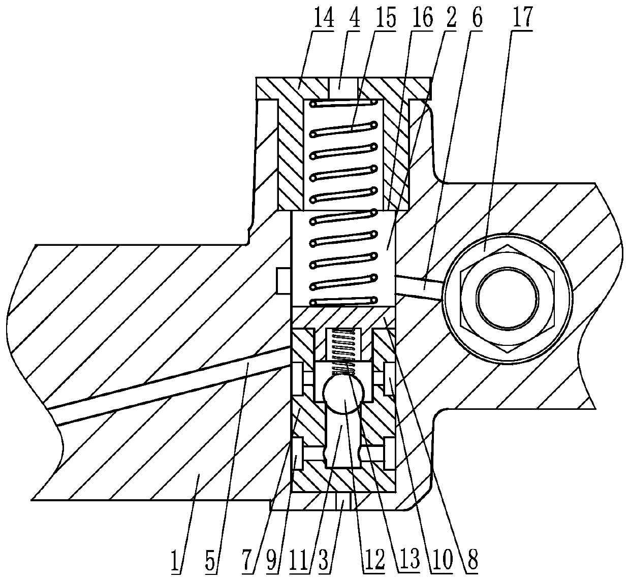
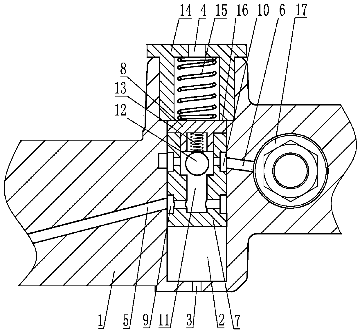
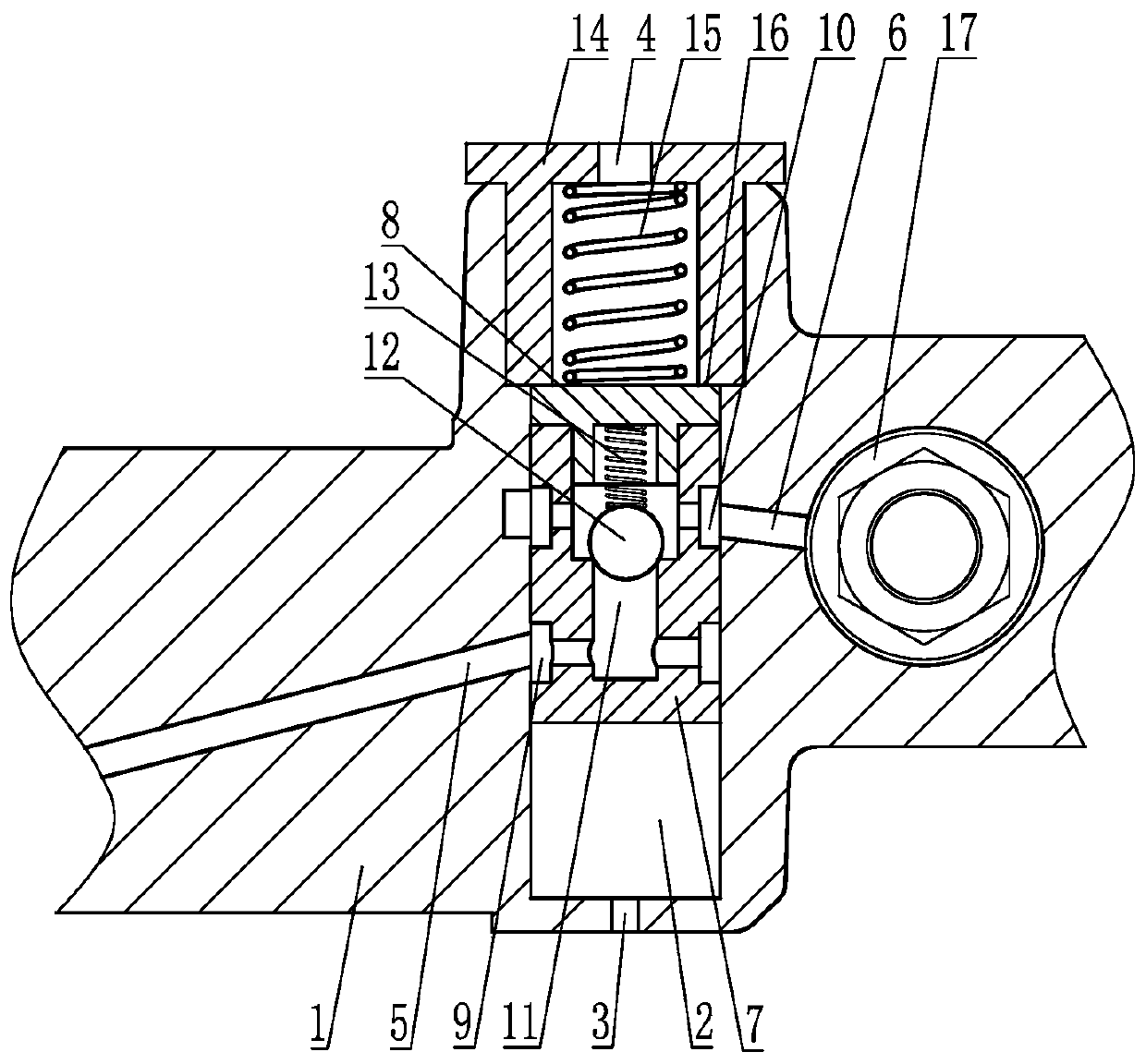
[0027] Such as Figure 1 to Figure 3As shown, the engine brake control device with multiple driving sources includes a support frame 1. In this embodiment, the support frame 1 is a rocker mechanism, and of course it can also be other moving parts or fixed parts. The support frame 1 A control valve cavity 2 is arranged inside, and a control valve assembly is slidably installed in the control valve cavity 2, and a braking...


PUM


Abstract

The invention discloses an engine brake control device with multiple driving sources. The device comprises a supporting frame, wherein a control valve cavity is arranged in the supporting frame, a control valve assembly is arranged in the control valve cavity in a sliding mode, a braking driving channel used for introducing the driving sources is arranged on the position, on one side of the control valve assembly, of the supporting frame, the braking driving channel communicates with the control valve cavity, a control valve returning device is arranged between the supporting frame and the other side of the control valve assembly, and an oil release and drainage channel communicating with the control valve cavity is arranged on the control valve returning device; a brake oil supplying channel and a brake oil filling channel are further arranged on the supporting frame, wherein the brake oil supplying channel and the brake oil filling channel both communicate with the control valve cavity; and the control valve assembly is in reciprocating motion in the control valve cavity to intermittently communicate a channel between the brake oil supplying channel and the brake oil filling channel with a channel between the brake oil filling channel and the oil release and drainage channel. The device has the advantages of being rapid in oil filling, short in braking reaction time, fast inbraking response and the like, and different driving sources can be selected to drive the control valve assembly.

Description

technical field [0001] The invention belongs to the technical field of engines, in particular to an engine braking control device with multiple driving sources. Background technique [0002] The total mass of modern cars is getting bigger and bigger, the speed is getting higher and higher, and the rolling resistance, wind resistance, and internal friction loss of the vehicle are getting smaller and smaller, which means that the deceleration ability of the vehicle itself is reduced; at the same time, due to the increase in the total mass of the vehicle , relying solely on the vehicle's own service braking system (commonly known as the foot brake) can no longer meet the braking requirements of the vehicle under high-speed and heavy-load conditions. Frequent pressing of the brakes for a long time will cause the brake pads to heat up, the braking effect will decrease or even the brakes will fail, which will endanger the safety of people and vehicles! [0003] In order to ensure...

Claims


Application Information

Patent Timeline
Patent Type & Authority Applications(China)
IPC IPC(8): F02D13/04
CPCF02D13/04F02D13/0276F02D13/0242F02D13/0253
Inventor 褚志强
Owner JIANSU JOINTEK PRECISION MASCH CO LTD
Learn More