Hydraulic control device of working machine

A technology for control devices and operating machinery, applied in fluid pressure actuators, mechanically driven excavators/dredgers, mechanical equipment, etc., can solve problems such as slow system response and complex oil circuits, and achieve fast system response, The effect of simplifying the oil circuit of the system and reducing the weight

Pending Publication Date: 2019-12-06
JIANGSU HENGLI HYDRAULIC TECH CO LTD
View PDF0 Cites 4 Cited by
  • Summary
  • Abstract
  • Description
  • Claims
  • Application Information

AI Technical Summary

Problems solved by technology

[0004] In order to solve the technical problems existing in the prior art of using bypass throttling for speed regulation control, the system oil circuit is compl

Method used


Image

  • Hydraulic control device of working machine
  • Hydraulic control device of working machine
  • Hydraulic control device of working machine

Examples


Embodiment Construction

[0036] The following will clearly and completely describe the technical solutions in the embodiments of the present invention with reference to the accompanying drawings in the embodiments of the present invention. Obviously, the described embodiments are only some, not all, embodiments of the present invention. The following description of at least one exemplary embodiment is merely illustrative in nature and in no way taken as limiting the invention, its application or uses. Based on the embodiments of the present invention, all other embodiments obtained by persons of ordinary skill in the art without creative efforts fall within the protection scope of the present invention.

[0037] It should be noted that the terminology used here is only for describing specific implementations, and is not intended to limit the exemplary implementations according to the present application. As used herein, unless the context clearly dictates otherwise, the singular is intended to include...


PUM


Abstract

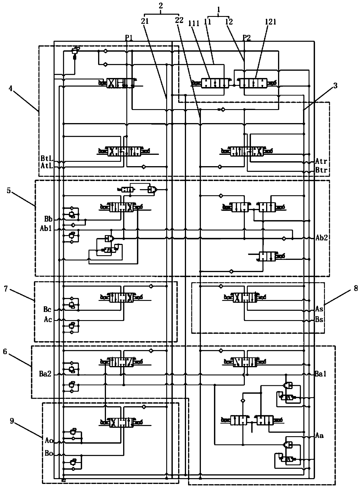
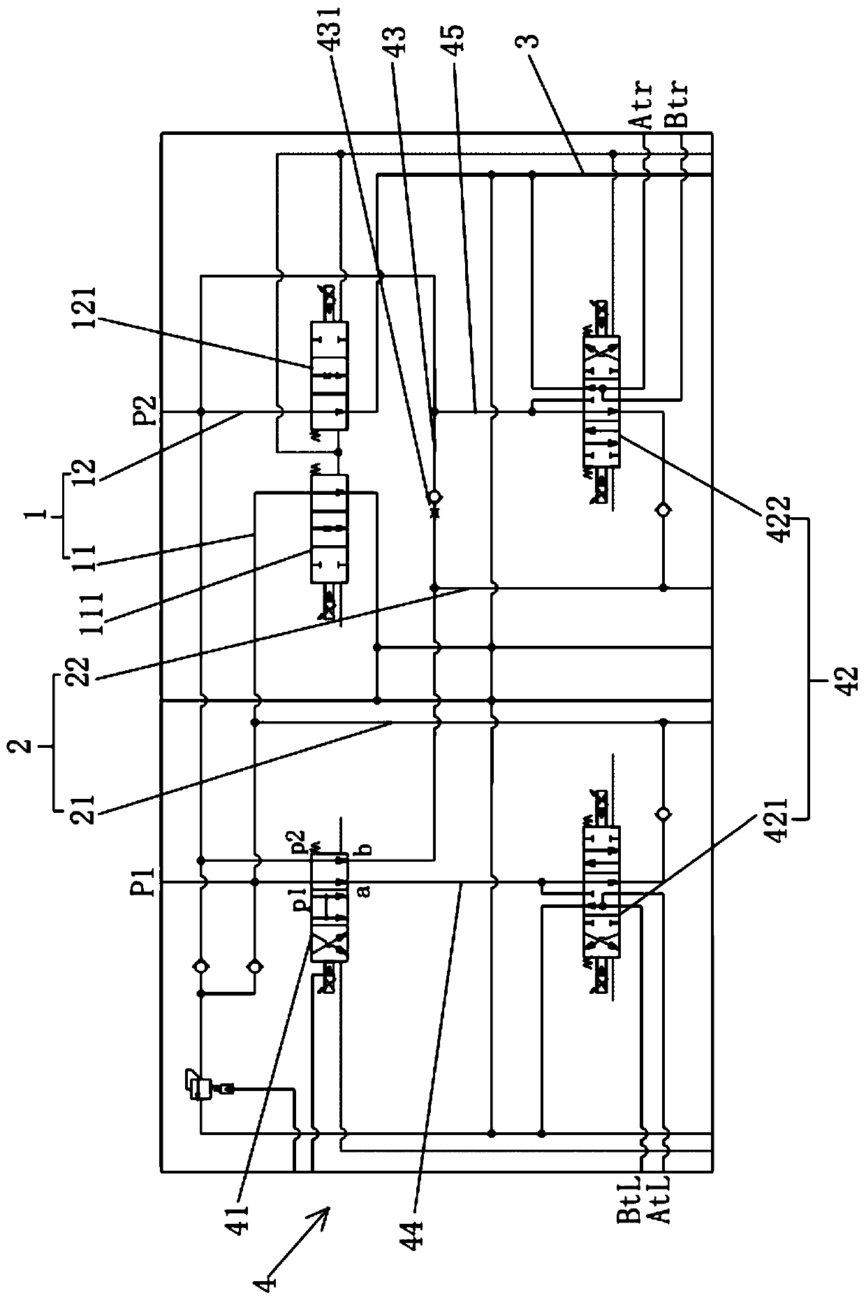
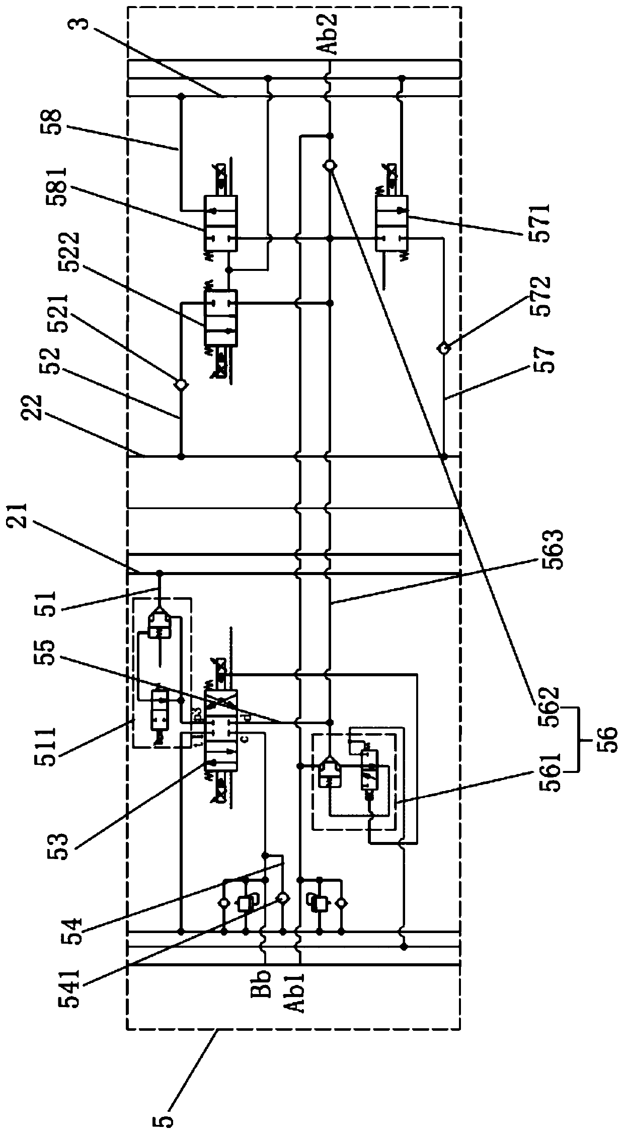
The invention relates to the field of hydraulic control, in particular to a hydraulic control device of a working machine. The hydraulic control device of the working machine comprises at least one hydraulic pump, at least one hydraulic actuator, at least one control valve and at least one oil discharging oil path, wherein the at least one hydraulic pump is used for spraying out working oil, the at least one hydraulic actuator is operated through the working oil supplied from the at least one hydraulic pump, the at least one control valve is arranged for each hydraulic actuator and conduct operation on the supply of the working oil from the hydraulic pump to the corresponding hydraulic actuator so as to correspondingly control the actions of the hydraulic actuators, the at least one oil discharging oil path is arranged for each hydraulic pump, the working oil pumped by each hydraulic pump can be directly returned through the oil discharging oil paths, the oil discharging oil paths areprovided with oil discharging valves, and the oil discharging valves control the connection and disconnection and oil flux of the oil discharging oil paths. The technical problems that in the prior art, the bypass throttling is adopted for speed regulation control, the system oil paths are complex and the system response is low are solved.

Description

technical field [0001] The invention relates to the field of hydraulic control, in particular to a hydraulic control device of an operating machine. Background technique [0002] Among the current construction machinery, the use of excavators has been greatly promoted and applied, and its fuel consumption, work efficiency and ease of operation are the main concerns of various main engine manufacturing companies, R&D institutions and customers. The working device of the excavator is composed of main parts such as the boom, the stick, the bucket, and the hydraulic pipeline of the working device including the boom cylinder, the stick cylinder, and the bucket cylinder. The stick is an important part of the working device of the excavator. Components, the reasonable setting of its hydraulic system is of great significance to the working performance of the excavator. [0003] The hydraulic system of the existing excavator has the following problems: 1. The structure of three-posi...

Claims


Application Information

Patent Timeline
IPC IPC(8): F15B11/00F15B13/02E02F3/42E02F9/22
CPCE02F3/42E02F9/2264E02F9/2267E02F9/2292F15B11/00F15B13/02F15B2211/20576
Inventor 汪立平刘红光贾靖哈良黄国和韩俊翔翟莉
Owner JIANGSU HENGLI HYDRAULIC TECH CO LTD
Why Eureka
Try Eureka