
Digital wire feeding system

A wire feeding system and wire feeding technology, applied in arc welding equipment, manufacturing tools, welding equipment, etc., can solve the problems of increased failure rate, long control period, and difficulty in taking into account thick and thin wires in the wire feeding system, and achieve uniform The effect of speed regulation and stability guarantee

Inactive Publication Date: 2008-02-13
SHANGHAI WTL WELDING EQUIP MFG CO LTD
View PDF6 Cites 0 Cited by
  • Summary
  • Abstract
  • Description
  • Claims
  • Application Information

AI Technical Summary

Problems solved by technology

Its main circuit adopts MOSFET as the single-end switch tube, and L, C, D switching power supply as the power supply of the armature group. Due to the long control period of the SCR, the response speed of the system is slow. When the grid voltage fluctuates in a large range , the compensation ability is poor, which affects the stability of wire feeding and causes fluctuations in welding specifications and welding quality
Moreover, the speed ratio of the general SCR-M speed control system is difficult to exceed 10, which makes it difficult for the same wire feeding system to take into account both thick and thin wires, which limits the current adjustment range of the welding machine, and accordingly makes the welding machine adaptability is limited
In addition, the system does not consider the situation that the voltage cannot be compensated when the wire feed line is too long during the welding process, which will be limited in actual use. Similarly, the system does not have a sudden brake function, which increases the failure rate during the welding process

Method used


Image

  • Digital wire feeding system
  • Digital wire feeding system

Examples


Embodiment Construction

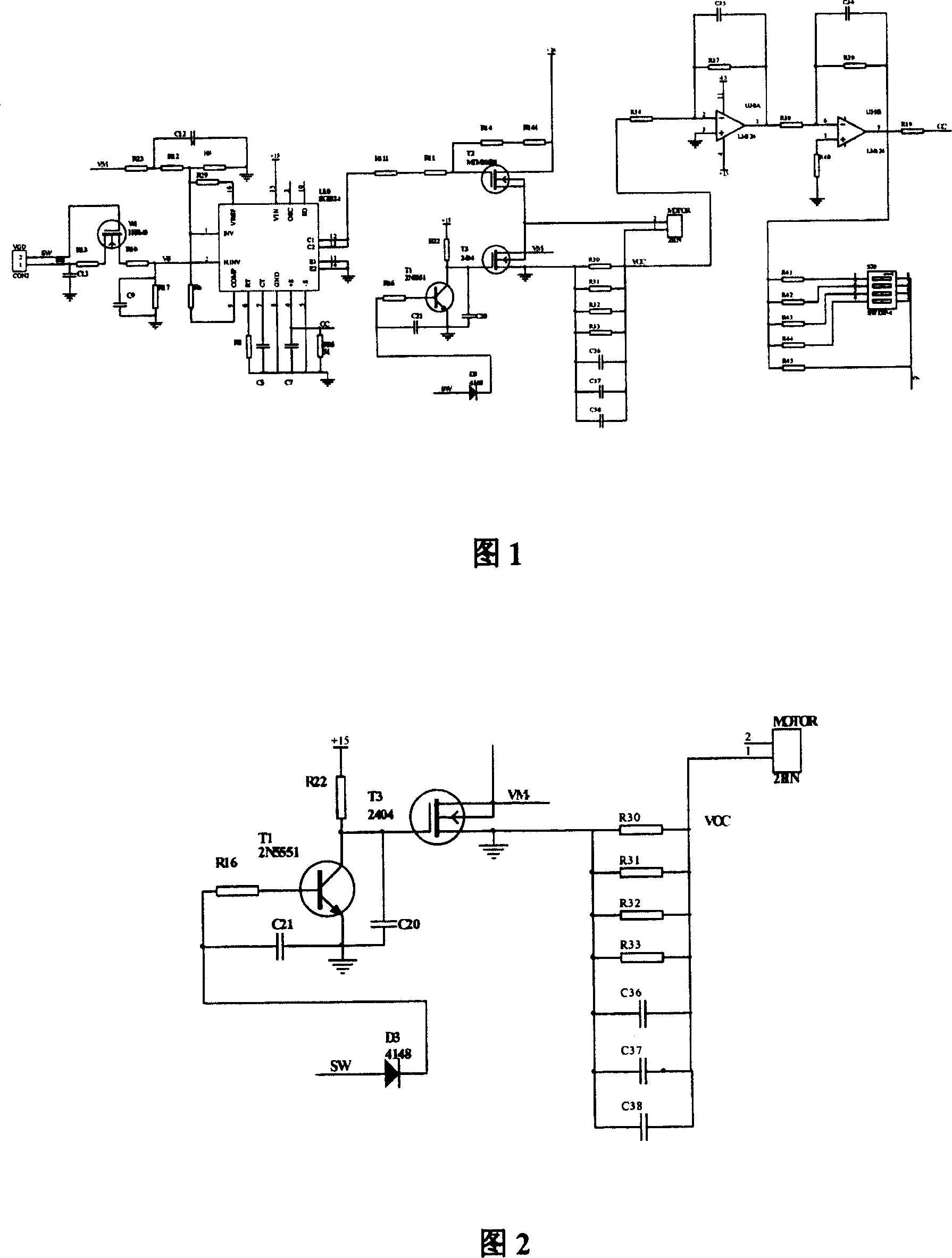
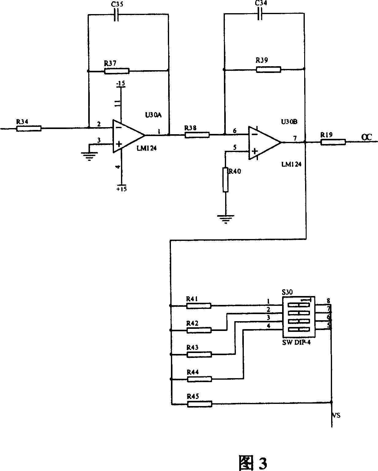
[0009] As shown in Figure 1: the digital wire feeding system of the present invention includes: a high-frequency modulation pulse circuit, an emergency brake circuit, and a wire feeding system lifting circuit. The working principle is described below in conjunction with the circuit diagram:

[0010] The given signal of wire feeding speed is given by the potentiometer on the wire feeder and is added to the collector terminal of MOSFET tube W1 through the 2 terminals of socket VGD. When the welding start signal SW is valid (high level), the gate of MOSFET tube T1 Extremely high level makes MOSFET T2 turn on, VGD signal enters the control terminal of PWM chip U10, which makes pins 12 and 13 of PWM chip U10 output pulses, and this pulse makes MOSFET T2 turn on, 24V The voltage is applied to the socket of the motor (MOTOR), so that the wire feeding motor is energized and operated, which is the working process of the pulse circuit. In this specific embodiment, the MOSFET W1 is IRF64...


PUM


Abstract

A digitalized wire feeding system for welding has a HF modulating pulse circuit. A given wire-feeding speed signal is applied to the collector of the MOSFET (W1). When the weld beginning signal is active, the high level at the gate of MOSFET (T1) can turn on the MOSFET (T2) and said wire-feeding speed signal is inputted to the control pin of PWM chip, which outputs a pulse to turn on the MOSFET (T2). A voltage is applied to the wire-feeding moto to rotate it.

Description

technical field [0001] The invention relates to a wire feeding system of a welding machine, in particular to a digital wire feeding system. Background technique [0002] The speed regulation system of the wire feeding motor in the welding machine system generally adopts the SCR-M system. Its main circuit adopts MOSFET as the single-end switch tube, and L, C, D switching power supply as the power supply of the armature group. Due to the long control period of the SCR, the response speed of the system is slow. When the grid voltage fluctuates in a large range , the compensation ability is poor, which affects the stability of wire feeding and causes fluctuations in welding specifications and welding quality. Moreover, the speed ratio of the general SCR-M speed control system is difficult to exceed 10, which makes it difficult for the same wire feeding system to take into account both thick and thin wires, which limits the current adjustment range of the welding machine, and ac...

Claims


Application Information

Patent Timeline
Patent Type & Authority Patents(China)
IPC IPC(8): B23K9/133
Inventor 尤志春
Owner SHANGHAI WTL WELDING EQUIP MFG CO LTD
Learn More