
Hydraulic rotary four-jaw clamp

A four-jaw clamp, hydraulic rotation technology, applied in manufacturing tools, auxiliary welding equipment, welding equipment, etc., can solve the problem of lack of fast and accurate operating mechanism, uneven quality of welding products, and low quality of clamping and welding work, etc. problems, to achieve the effect of simple structure, convenient disassembly and assembly, and prevention of leakage

Active Publication Date: 2020-10-09
东莞市富锐精密五金制品有限公司
View PDF11 Cites 0 Cited by
  • Summary
  • Abstract
  • Description
  • Claims
  • Application Information

AI Technical Summary

Problems solved by technology

However, in the process of practical work at the present stage, the clamping methods adopted for pipe parts are either traditional special fixtures or combined fixtures that are expensive and complex in structure. For traditional special fixtures, not only requires a lot of manpower, It does not have a fast and accurate operating mechanism, and cannot automatically rotate itself, causing inconvenience to welding personnel, resulting in low quality clamping and welding work, and uneven quality of welding products
In addition, the safety performance of traditional special fixtures is not perfect

Method used


Image

  • Hydraulic rotary four-jaw clamp
  • Hydraulic rotary four-jaw clamp
  • Hydraulic rotary four-jaw clamp

Examples


Embodiment 1

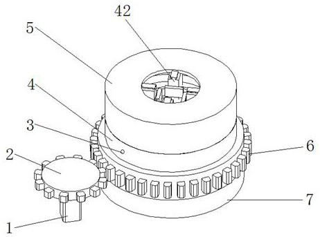
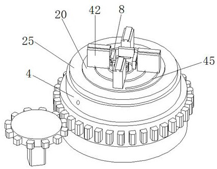
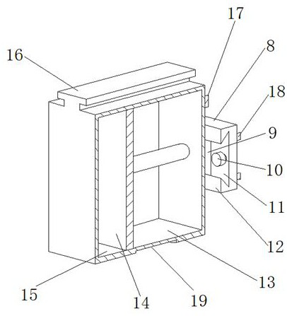
[0029] Embodiment 1: hydraulically rotating four-jaw fixture, constituted as Figure 1-6 Shown includes the chuck body 4, the material of the chuck body 4 is low carbon steel, the upper part of the chuck body 4 is fixed with a ring bracket 5, the ring bracket 5 is provided with a first through hole 27, and the inner side of the ring bracket 5 is provided with a T-shaped Groove 26; Chuck body 4 below is provided with support assembly 7, and described support assembly 7 comprises circular ferrule 37, and circular ferrule 37 top is provided with second circular groove 44, and the center of second circular groove 44 is provided with The third through hole 46, the top of the circular ferrule 37 is fixed with the chuck body 4, the second circular groove 44 and the third through hole 46 form a hollow part, and the hollow part is pierced with the fixed shaft 30, and the circular ferrule 37 can be Rotates around a fixed axis 30 . The side of the chuck body 4 is provided with a rack 6,...


PUM


Abstract

The invention discloses a hydraulic rotary four-claw clamp. The hydraulic rotary four-claw clamp comprises a chuck body, wherein an annular bracket is arranged above the chuck body, and T-shaped grooves are formed in the annular bracket; racks are arranged on the side surface of the chuck body and are connected with a gear and a stepping motor; an oil disc is fixed on the chuck body, a cone toothtable is arranged above the oil disc, convex rails are arranged on the cone tooth table, four clamping claws are arranged above the cone tooth table, T-shaped convex strips matched with the T-shaped grooves are arranged at the upper parts of the clamping claws, and arc-shaped grooves matched with the convex rails are formed in the lower parts of the clamping claws; a fixed clamping plate is fixedon the inner side of the oil disc, an oil disc oil inlet cavity is formed in one side of the fixed clamping plate, and an oil disc oil outlet cavity is formed in the other side of the fixed clamping plate; and a pushing plate is arranged outside the cone tooth table, the oil disc oil inlet cavity is connected with a hole A of a first reversing valve, holes B, T and P of the first reversing valve are respectively connected with the oil disc oil outlet cavity, an oil tank and an oil pump, and the oil pump is connected with the oil tank. The hydraulic rotary four-claw clamp has the characteristics of simple structure, convenience in disassembly and safety in operation.

Description

technical field [0001] The invention relates to a four-claw clamp, in particular to a hydraulically rotating four-claw clamp. Background technique [0002] In today's society, welding fixture design is one of the most critical work contents in the production preparation process in the field of mechanical manufacturing. At the same time, in the process of welding production process design, welding fixture design is also one of the most critical components. For many mechanical manufacturing and processing fields, if there is no technical support and guarantee provided by welding fixtures, there will be no final welding products. However, in the process of practical work at the present stage, the clamping methods adopted for pipe parts are either traditional special fixtures or combined fixtures that are expensive and complex in structure. For traditional special fixtures, not only requires a lot of manpower, It also does not have a fast and accurate operating mechanism, and ...

Claims


Application Information

Patent Timeline
Patent Type & Authority Patents(China)
IPC IPC(8): B23K37/04B23K37/047B23B31/16B23B31/30
CPCB23B31/16B23B31/302B23K37/04B23K37/047
Inventor 陈建生陈敏
Owner 东莞市富锐精密五金制品有限公司
Learn More