Supercharge Your Innovation With Domain-Expert AI Agents!

Osmotic pressure-driven two-phase fluid loop

A fluid circuit, osmotic pressure technology, applied in lighting and heating equipment, indirect heat exchangers, etc., can solve problems such as insufficient capillary driving force, insufficient capillary driving force, and insufficient liquid stability, and achieve flow distribution. Uneven and mutual interference problems, improve transmission distance and heat transfer capacity, and achieve simple and easy results

Pending Publication Date: 2019-12-06
BEIJING INST OF SPACECRAFT SYST ENG
View PDF7 Cites 0 Cited by
  • Summary
  • Abstract
  • Description
  • Claims
  • Application Information

AI Technical Summary

Problems solved by technology

[0008] (1) The capillary driving force is not strong enough
For high power (above 1kW), ultra-long-distance heat transfer (such as greater than 30m), anti-gravity work or overload environment, the capillary driving force is not enough. The conventional loop heat pipe uses a 1μm capillary core, which is not suitable for ammonia working fluid. It can only provide a driving force of no more than 100kPa, and even if a 0.3μm capillary core is used, the capillary force does not exceed 300kPa, and reducing the pore size of the capillary core will also bring about problems related to the increase of liquid flow resistance in the core
[0009] (2) There is instability
The capillary wick sucks the liquid in the condenser back to the evaporator through capillary force. Only by capillary force, the liquid from the liquid pipeline to the liquid trunk is not stable enough. Once evaporation or boiling occurs, it is easy to cause unstable operation of the circuit (temperature fluctuations, backflow, temperature hysteresis, etc.) or even affect the liquid supply and cause failure
[0010] (3) Each branch in the parallel system will affect each other
When multiple evaporators are connected in parallel and the working conditions of each branch are different, there may be flow interference in each branch, insufficient liquid supply or start-up problems

Method used


Image

  • Osmotic pressure-driven two-phase fluid loop
  • Osmotic pressure-driven two-phase fluid loop
  • Osmotic pressure-driven two-phase fluid loop

Examples


Embodiment Construction

[0029] The present invention will be described in detail below with reference to the accompanying drawings and examples.

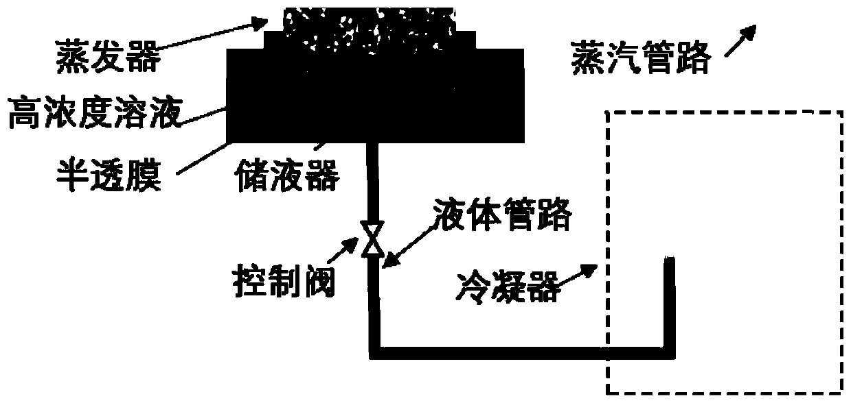
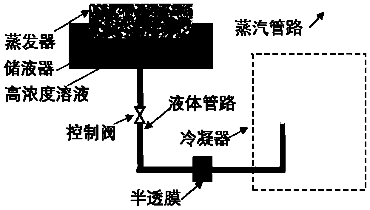
[0030] The present invention provides a two-phase fluid circuit driven by osmotic pressure.

[0031] The two-phase fluid circuit includes a liquid receiver, an evaporator, a steam pipeline, a condenser and a liquid pipeline. The working medium in the liquid receiver enters the evaporator under the action of a driving force and becomes gaseous, and the gaseous working medium arrives through the steam pipeline. Condenser, the heat of the working medium is transferred to the equipment through the condenser, the gaseous working medium in the circuit becomes liquid, and the liquid working medium returns to the liquid receiver through the liquid pipeline; the working medium circulates continuously under the action of the driving force to realize heat transfer . The loop is similar to a loop heat pipe, forming a vacuum loop in which the vapor / liquid working medi...


PUM


Abstract

The invention discloses an osmotic pressure-driven two-phase fluid loop. The osmotic pressure-driven two-phase fluid loop is big in driving force; in addition, no energy supply is needed; stability ishigh; the heat transmission capacity is high; and the heat transmission distance is long. According to the osmotic pressure-driven two-phase fluid loop, a semipermeable membrane is arranged in a liquid accumulator or a liquid pipeline, and a solute soluble in a working medium is added to part of the working medium on the semipermeable membrane; the boiling point of the solute is higher than the temperature of an evaporator; and the semipermeable membrane is used for passing of the working medium and not for passing of the solute. According to the osmotic pressure-driven two-phase fluid loop,osmotic pressure is adopted as the driving force; operation of the two-phase fluid loop is achieved; a brand-new fluid loop driving manner is achieved; the loop is simple and practicable, the drivingforce is big, and the driving force is completely passive driving force; no energy supply is needed, and the problem of mechanical component loss does not exist; besides, the driving force is big, loop hot pipe driving force can be improved conspicuously, and the transmission distance and the heat transferring capacity are improved; and stability is high, a loop heat pipe can be in a fixed thermalconductive working state all the time, and the phenomenon of instability caused by heat leakage to the liquid accumulator by the evaporator is avoided.

Description

technical field [0001] The invention relates to the technical field of equipment heat dissipation, in particular to the efficient heat transfer of spacecraft and other electronic equipment on the ground, and in particular to a two-phase fluid circuit driven by osmotic pressure. Background technique [0002] The two-phase fluid circuit relies on the latent heat of the working fluid to achieve heat transfer. Compared with the single-phase fluid circuit and traditional heat pipes, it has the characteristics of large heat transfer, small temperature difference, long-distance heat transfer, and excellent temperature control characteristics. Due to the incomparable advantages of many other heat transfer devices, the two-phase fluid circuit has been a key development of spacecraft thermal control technology in the past ten years. [0003] According to the driving mode, the two-phase fluid circuit technology mainly includes: two-phase fluid circuit driven by mechanical pump and two-...

Claims


Application Information

Patent Timeline
Patent Type & Authority Applications(China)
IPC IPC(8): F28D15/04F28D15/06
CPCF28D15/043F28D15/06
Inventor 张红星李国广任校志何江苗建印
Owner BEIJING INST OF SPACECRAFT SYST ENG
Features
  • R&D
  • Intellectual Property
  • Life Sciences
  • Materials
  • Tech Scout
  • Unparalleled Data Quality
  • Higher Quality Content
  • 60% Fewer Hallucinations
Learn More