Relay capable of reducing contact jitter

A contact vibration and relay technology, applied in the direction of relays, electromagnetic relays, electromagnetic relay details, etc., can solve the problems of unfavorable moving reeds working efficiently, hindering normal breakpoint action, increasing the probability of contact bonding, etc., to achieve effective Conducive to miniaturization design, reduce vibration phenomenon, avoid the effect of arc reignition

Pending Publication Date: 2019-12-06
XIAMEN HONGFA ELECTRIC POWER CONTROLS
View PDF0 Cites 1 Cited by
  • Summary
  • Abstract
  • Description
  • Claims
  • Application Information

AI Technical Summary

Problems solved by technology

[0004] During the operation of the relay, the kinetic energy of the pushing card and the moving reed is relatively large. During the contact switching process, when the contacts are closed, the pushing card and the moving reed will vibrate back and forth due to the above kinetic energy and inertia, and the pushing The shaking frequency and amplitude of the card and the moving reed are different. During the process, there will be a short separation between the "H"-shaped connection part and the moving reed, which will cause the contact bounce of the contact, which will cause An arc is generated between the contacts, which increases the bonding probability of the contacts; when the contacts are broken, the movable contact will vibrate due to the kinetic energy of the above-mentioned push card and the movable reed, resulting in the maximum and minimum contact gaps , when the contact gap is at a minimum, it is easy to cause arc reignition
[0005] When the "H" type connecting part pushes the moving contact of the moving spring part to disconnect from the static contact of the static spring part, it is easy to interfere with the lead-out piece of the moving spring on the volume of the existing relay, hindering the normal breakpoint action
In order to avoid interference, it is necessary to design the moving spring lead-out piece to be far enough away from the moving reed in the moving direction of the push card, which is not conducive to the efficient work of the moving spring; or design the moving spring lead-out piece to be in the "H" type If the height direction of the connection part is far enough away from the push card, the volume of the relay will increase
[0006] During the installation process of the "H" type connection part and the moving reed, scratches inevitably occur, resulting in production problems of debris

Method used


Image

  • Relay capable of reducing contact jitter
  • Relay capable of reducing contact jitter
  • Relay capable of reducing contact jitter

Examples


Embodiment 1

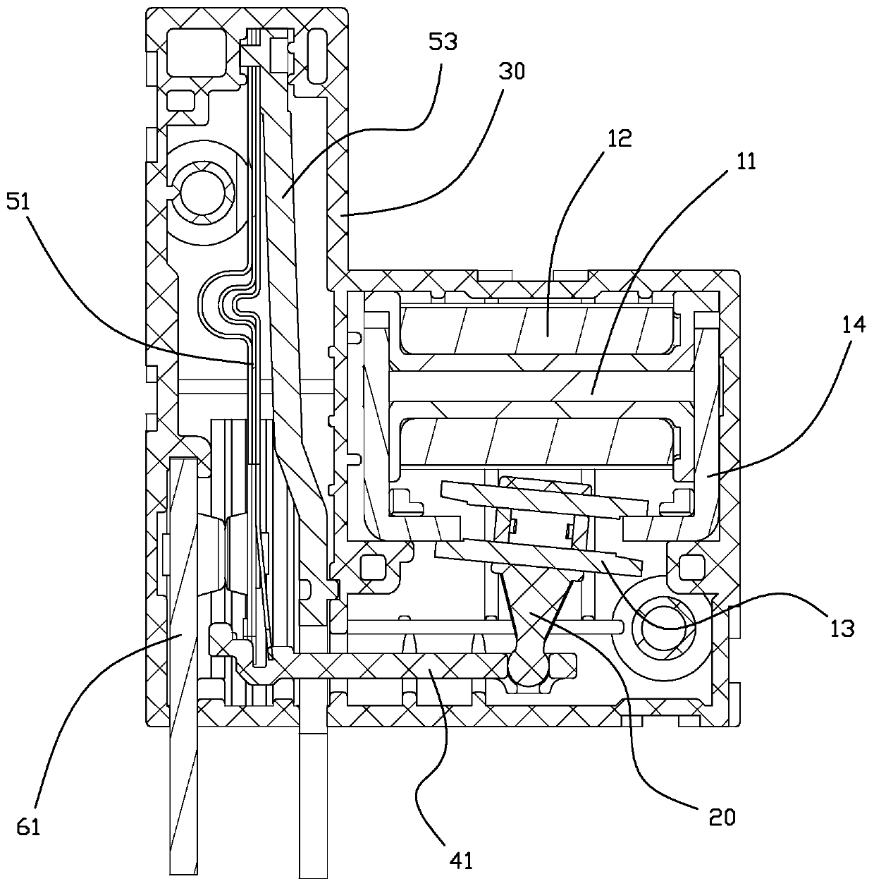
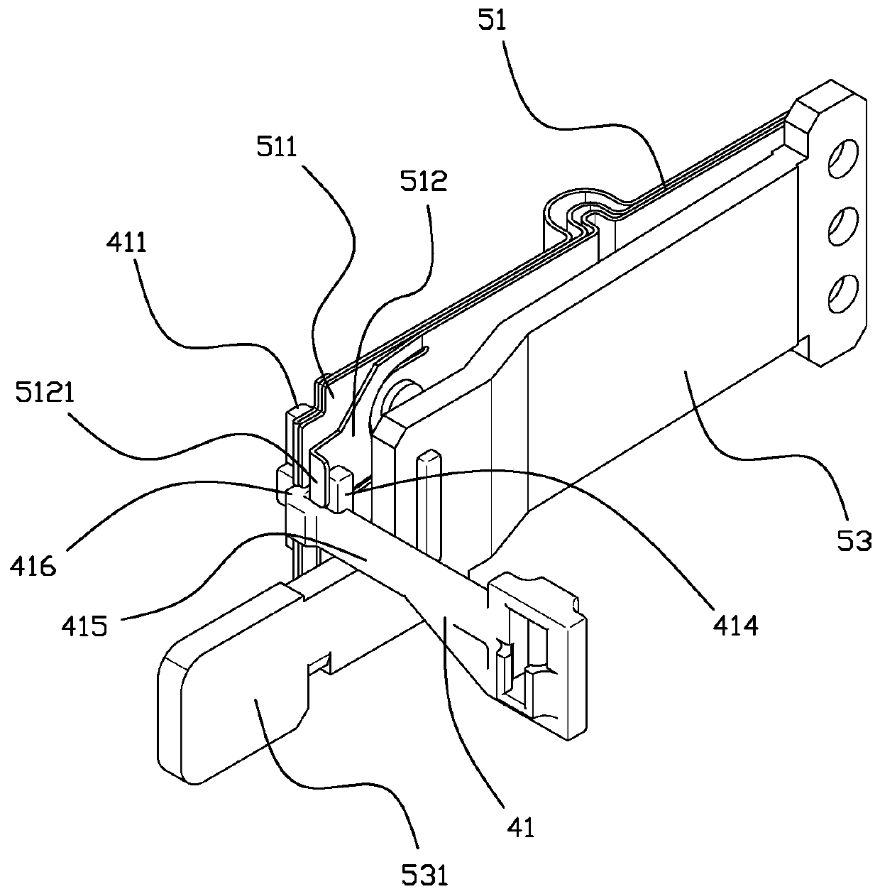
[0042] In order to solve the problems existing in the prior art, such as the large jitter of the moving spring part and the interference between the push-pull rod and the lead-out piece of the moving spring, the present invention provides a relay with reduced contact jitter, such as Figure 1 to Figure 6As shown, the relay described in this embodiment includes a magnetic circuit system, a contact system, a push member 20 and a base 30; the magnetic circuit system is composed of an iron core 11, a coil 12, an armature 13 and a yoke 14, and the contact system is provided with Push-pull rod 41, moving spring part, static spring part. The moving spring part includes a moving reed 51, a moving contact 52 and a moving spring lead-out piece 53, and the static spring part includes a static reed 61 and a static contact 62, and the moving reed 51 and the static reed 61 are respectively arranged on matching Position; the root of the movable reed 51 is fixed, and the movable contact 52 is...

Embodiment 2

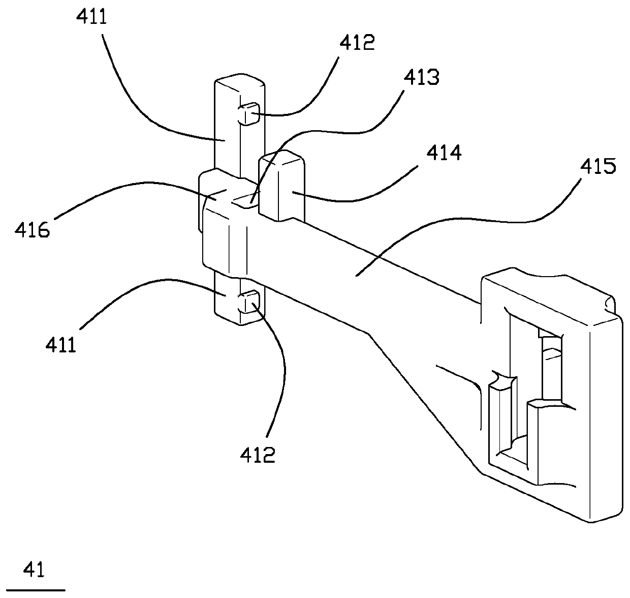
[0058] The difference between this embodiment and Embodiment 1 is that the width of the slot 413 is different, such as Figure 9 , Figure 10 As shown, in this embodiment, the connection between the slot 413 and the counter force reed 512 is clearance fit, that is, when the counter force reed 512 is set in the slot 413, the width of the slot 413 is equal to that of the blocking surface 4132 and There is a certain gap in the counter force reed 512, so that gap installation is realized. At the same time, in order to ensure that the rebound distance is within the preset effect, a micro gap is set between the blocking surface 4132 of the slot 413 and the reaction force spring 512, which is convenient for assembly while ensuring that the rebound is reduced.

[0059]During specific implementation, the maximum amplitude of the counterforce reed 512 in an unrestricted state is affected by the performance of the magnetic circuit system, the work efficiency of the push-pull rod 41, the...


PUM


Abstract

The invention relates to a relay capable of reducing contact jitter. A pulling block cooperates with a clamping groove, so as to respectively locate a main body movable reed and a counter-force reed;especially, the clamping groove effectively limits the jitter stroke of the counter-force reed, thereby avoiding the idle stroke caused by kinetic energy in the action process, reducing the jitter ofthe movable reed part in the contact closing process, reducing the springback, avoiding the electric arcs generated between contacts due to springback, and reducing the bonding probability of the contacts. In the breaking process of the contact, the vibration phenomenon of the movable contact is reduced, and the situation of electric arc reignition is avoided. A push-pull rod effectively fixes themovable reed part through the combination of the pull block and the clamping groove, and solves the interference problem at one side close to a movable reed leading-out piece, so that the design of the movable reed leading-out piece is simpler, and the miniaturization design of the relay is facilitated. The pulling block is contacted with the main body movable reed through a convex bract, so thatthe stressed position of the main body movable reed can be fixed, and furthermore, the contact disconnection positions are consistent.

Description

technical field [0001] The invention relates to the technical field of relays, in particular to a relay with reduced contact vibration. Background technique [0002] A magnetic latching relay is usually composed of a magnetic circuit part, a contact part, a pushing mechanism and a base. The magnetic circuit part is generally composed of two basically symmetrical magnetic circuits, including a stationary magnetizer part, a movable magnetizer part and a coil, the contact part includes a moving spring part and a static spring part, and the push mechanism mainly includes a push card. The relay coil passes the positive pulse voltage, the magnetic circuit part works, pushes the card to push the moving spring part, so that the moving contact of the moving spring part contacts the static contact of the static spring part, the relay operates, the coil passes the reverse pulse voltage, and the magnetic circuit The circuit part works, push the card to push the moving spring part, so t...

Claims


Application Information

Patent Timeline
Patent Type & Authority Applications(China)
IPC IPC(8): H01H50/58
CPCH01H50/58
Inventor 钟叔明代文广李方能郑增光张杰郎
Owner XIAMEN HONGFA ELECTRIC POWER CONTROLS
Why Eureka
Try Eureka