Signal transmission circuit and signal transmission method

A signal transmission and circuit technology, applied in the direction of transducer circuit, circuit or fluid pipeline, negative feedback circuit layout, etc., can solve the problems of PSRR reduction, low gain, complicated circuit design, etc., and achieve the effect of easy manufacturing

Inactive Publication Date: 2019-12-06
YAMAHA CORP
View PDF3 Cites 2 Cited by
  • Summary
  • Abstract
  • Description
  • Claims
  • Application Information

AI Technical Summary

Problems solved by technology

[0022] In addition, when bipolar transistors are used to amplify audio signals, even if an attempt is made to suppress the influence of noise (that is, audio signals) superimposed on the power supply voltage of the common wiring, the gain is low, so PSRR cannot be improved. reduce
[0023] Therefore, since the PSRR cannot be reduced, the accuracy in the signal transmission of the audio signal cannot be improved, and the amplification factor is limited to a low value.
[0024] In addition, the setting of constants such as resistors and capacitors for increasing the amplification factor and PSRR, that is, circuit design is complicated, and it is difficult to set the amplification factor and PSRR between different transmission circuits due to fluctuations in the manufacture of bipolar transistors. stable value

Method used


Image

  • Signal transmission circuit and signal transmission method
  • Signal transmission circuit and signal transmission method
  • Signal transmission circuit and signal transmission method

Examples


no. 1 Embodiment approach

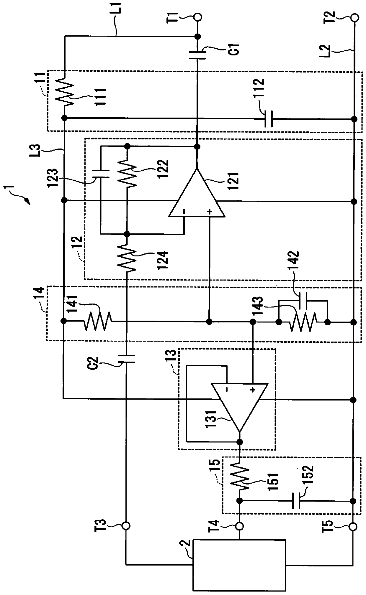
[0047] Next, the signal transmission circuit according to the first embodiment of the present invention will be described with reference to the drawings. figure 1 It is a diagram showing a circuit example of the signal transmission circuit according to the first embodiment of the present invention.

[0048] exist figure 1 Among them, the signal transmission circuit 1 has a first low-pass filter 11, an amplification unit 12, a bias power generation unit 13, a reference voltage generation unit 14, a second low-pass filter 15, a first DC blocking capacitor C1, and a second blocking capacitor C1. Straight capacitor C2.

[0049] The first low-pass filter 11 removes signal components in the voice band (smoothes the signal of the common wiring) from the signal of the common wiring L1 (power supply signal as a DC signal described later) and smoothes the signal Filter output to power supply wiring L3. That is, the first low-pass filter 11 is to superimpose the audio signal ( The ...

no. 2 Embodiment approach

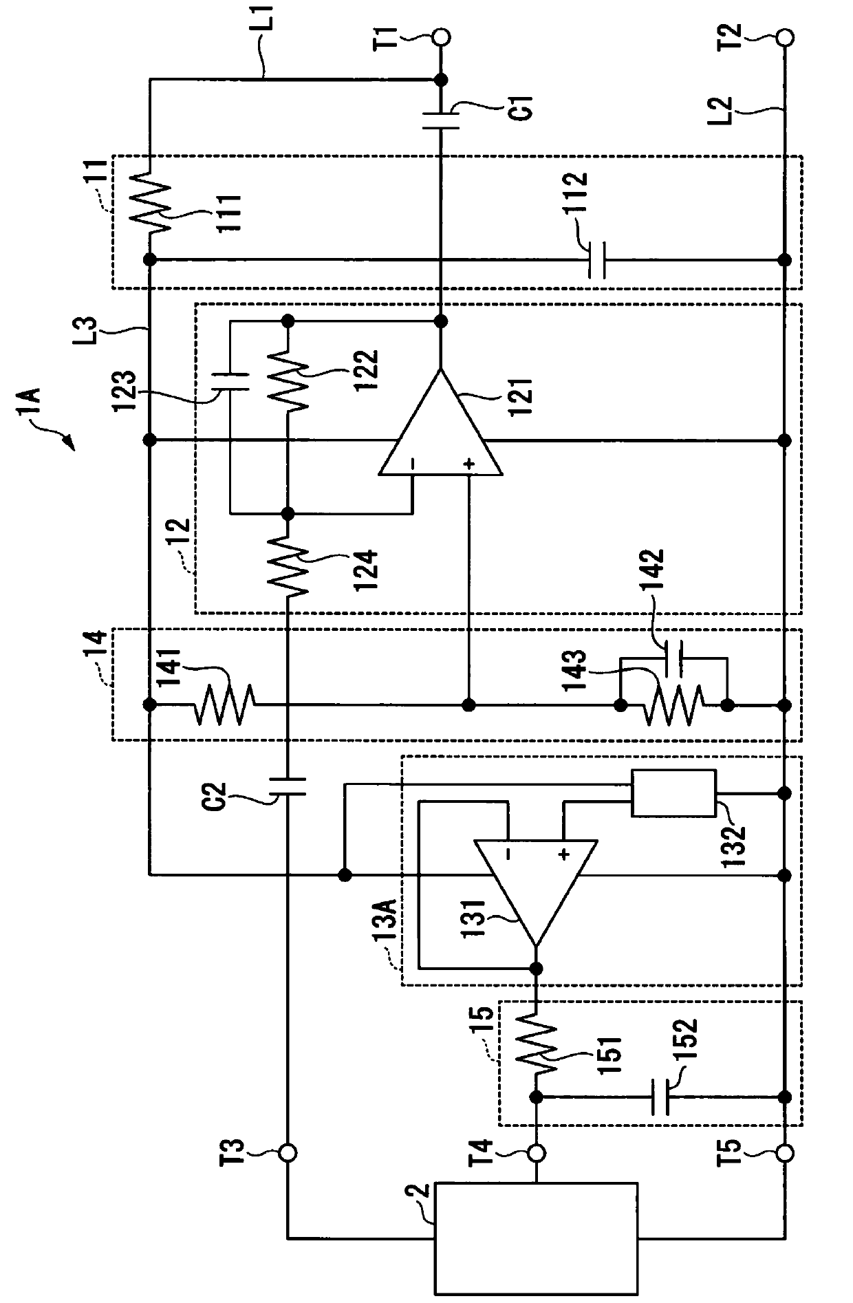
[0077] Next, a signal transmission circuit according to a second embodiment of the present invention will be described with reference to the drawings. figure 2 It is a diagram showing a circuit example of the signal transmission circuit according to the second embodiment of the present invention.

[0078] exist figure 2 Among them, the signal transmission circuit 1A has a first low-pass filter 11, an amplification unit 12, a bias power generation unit 13A, a reference voltage generation unit 14, a second low-pass filter 15, a first DC blocking capacitor C1, and a second blocking capacitor C1. Straight capacitor C2.

[0079] The signal transmission circuit 1A differs from the first embodiment in that a bias power generation unit 13A is provided instead of the bias power generation unit 13 in the first embodiment. Hereinafter, only points different from the first embodiment will be described.

[0080] The bias power generation unit 13A has an operational amplifier 131 and a...


PUM


Abstract

The invention provides a signal transmission circuit and a signal transmission method. When each of a power supply wiring for supplying power, a GND line, and a signal line for transmitting a measurement signal is configured by two lines, PSRR can be improved, a measurement signal can be transmitted with a predetermined precision, a constant of a circuit can be simply determined, and the PSRR andthe amplification factor of the measurement signal can be stably and easily manufactured without fluctuation between individuals. The signal transmission circuit according to the present invention isprovided with: a common wiring for supplying a power supply and transmitting a signal; a signal amplification unit having a first operational amplifier for outputting the measurement signal amplifiedusing the power supply to the common wiring; a bias power supply generation means for generating, using a second operational amplifier, a bias power supply used when acquiring the measurement signal from the sensor device on the basis of the power supply; a first low-pass filter provided between the common wiring and the power supply terminals of the first and second operational amplifiers; and aground wiring connected to the ground terminals of the signal amplification unit and the bias power supply generation unit.

Description

technical field [0001] The present invention relates to a signal transmission circuit and a signal transmission method for amplifying a small-amplitude input signal and outputting it to another next-stage device. Background technique [0002] Currently, there is a signal output circuit that amplifies a small-amplitude sound signal (electrical signal) output by a small microphone such as ECM (Electret Condenser Microphones) or MEMS (Micro Electrical Mechanical Systems) and transmits it to a next-stage circuit (for example, refer to Non-Patent Document 1 and Non-Patent Document 2). [0003] If the transmission distance of the audio signal from the microphone to the next-stage circuit is, for example, a short distance of about 50 mm, less noise signal is superimposed on the signal line for transmitting the audio signal. [0004] Even if the output impedance of the microphone is high, the transmission distance is short, and the superimposed noise signal is small, so it is possi...

Claims


Application Information

Patent Timeline
Patent Type & Authority Applications(China)
IPC IPC(8): H04R3/00H03F1/34H03H11/04B60R16/023
CPCB60R16/0232H03F1/34H03F2200/03H03H11/04H03H2011/0477H04R3/00
Inventor 辻信昭
Owner YAMAHA CORP
Why Eureka
Try Eureka