A kind of laser sintering equipment

A laser sintering and equipment technology, applied in the field of additive manufacturing, can solve the problems of air holes, poor sealing effect, and difficulty in scraping of parts, and achieve the effect of improving efficiency, improving the quality of powder laying, and feeding powder uniformly.

Active Publication Date: 2022-04-22
SHAANXI HENGTONG INTELLIGENT MACHINE
View PDF5 Cites 0 Cited by
  • Summary
  • Abstract
  • Description
  • Claims
  • Application Information

AI Technical Summary

Problems solved by technology

[0002] In the laser sintering technology, the traditional molding equipment must use the workbench, that is, the processing is carried out on the workbench. Since the workbench and the forming cylinder wall are sealed by sealing gaskets, it is inevitable that the sealing effect is not good. question
[0003] In addition, the molding quality of parts is largely determined by the quality of powder coating. If the quality of powder coating is not high, the powder coating effect will not be good. If the powder contains pores and is uneven, the processed parts will have defects such as pores and poor structure.
The current methods of powder spreading and scraping in some technologies are not satisfactory. For example, after powder spreading in many powder spreading devices, the powder is unevenly distributed on the workbench, making it difficult to scrape.

Method used


Image

  • A kind of laser sintering equipment
  • A kind of laser sintering equipment

Examples


Embodiment 1

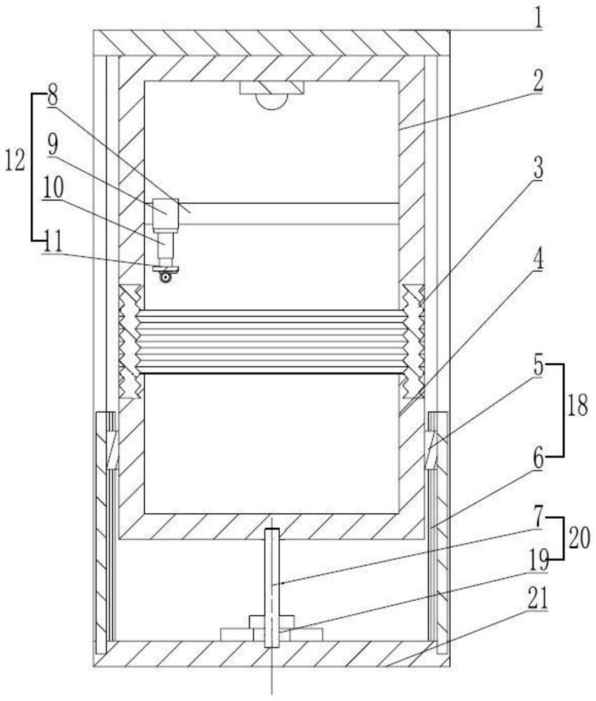
[0033] Embodiment 1: refer to figure 1 with figure 2 , a laser sintering printer, including a frame 1, an upper cylinder body 2, a lower cylinder body 4, a powder spreading mechanism 12, an orientation guide rail 18, a screw nut pair 20 and a telescopic structure 3.

[0034] In this embodiment, the upper and lower cylinder bodies are fixedly connected with the telescopic structure 3 through fitting, so that the entire molding cylinder is a closed space; the screw nut pair 20 is located at the center of the outer bottom of the lower cylinder body 4, It is consistent with the Z-axis direction of the cylinder body; the lower cylinder body 4 is provided with a directional guide rail 18 that supports the cylinder body and cooperates with the lead screw and nut pair 20 to make the lower cylinder body 4 move up and down.

[0035]The directional guide rail 18 includes a slider 5 and a static guide rail 6, and the static guide rail 6 is fixed on the lower mounting plate 21 of the fra...

Embodiment 3

[0049] The difference between this embodiment and Example 1 is that the diameter of the powder outlet hole on the powder outlet sieve is 70um. The purpose of this design is to adapt to the particle size of the powder. If the particle size of the powder is below 70um, the powder outlet sieve Powders with a diameter greater than 70um will be filtered, because in 3D printing, powders whose diameter does not meet the requirements will reduce the printing quality.

[0050] The working mode and other structures and connection modes of this embodiment are the same as those in Embodiment 1.

Embodiment 4

[0052] The difference between this embodiment and embodiment 1 is only that the diameter of the powder outlet hole on the powder outlet sieve is 120um, and its purpose is consistent with that described in embodiment 3, that is, if the particle size of the powder is below 120um, the powder outlet sieve will Filter powders with a diameter greater than 120um, because in 3D printing, powders whose diameter does not meet the requirements will reduce the printing quality.

[0053] The working mode and other structures and connection modes of this embodiment are the same as those in Embodiment 1.


PUM


Abstract

The invention discloses a laser sintering equipment, which belongs to the field of additive manufacturing, and includes a frame, a cylinder body, and a screw nut pair, and is characterized in that: the cylinder body includes an upper cylinder body and a lower cylinder body, and the upper and lower cylinder bodies Connected by a telescopic structure; the screw nut pair is located at the center of the bottom end of the lower cylinder body, which is consistent with the Z-axis direction of the cylinder body; the lower cylinder body is equipped with a supporting cylinder body and cooperates with the screw nut pair to make the lower cylinder body lift Moving directional guide rails; the powder supply and spreading mechanism includes a powder supply and spreading cover and a screw powder feeding mechanism; compared with the prior art, the scheme adopted by the present invention can completely solve the sealing and cleaning problems, and the scraping and spreading The powder is combined together, and the powder is scraped while spreading to improve the efficiency; the powder feeding mechanism is used to send the powder from one end of the powder supply and spreading sleeve to the other end, so as to achieve uniform powder feeding and improve the quality of powder spreading.

Description

technical field [0001] The invention relates to the field of additive manufacturing, in particular to a laser sintering device. Background technique [0002] In the laser sintering technology, the traditional molding equipment must use the workbench, that is, the processing is carried out on the workbench. Since the workbench and the forming cylinder wall are sealed by sealing gaskets, it is inevitable that the sealing effect is not good. question. [0003] In addition, the molding quality of parts is largely determined by the quality of powder coating. If the quality of powder coating is not high, the powder coating effect will not be good. If the powder contains pores and is uneven, the processed parts will have defects such as pores and poor structure. . The powder spreading and scraping methods in some technologies are not satisfactory in implementation. For example, after powder spreading in many powder spreading devices, the powder is unevenly distributed on the work...

Claims


Application Information

Patent Timeline
Patent Type & Authority Patents(China)
IPC IPC(8): B29C64/153B29C64/20B29C64/214B29C64/245B29C64/255B29C64/321B33Y30/00B33Y40/00
CPCB29C64/153B29C64/20B29C64/214B29C64/245B29C64/255B29C64/321B33Y30/00B33Y40/00
Inventor 郑力铭康柱黄继霖吴春蕾康小青尹海龙
Owner SHAANXI HENGTONG INTELLIGENT MACHINE
Why Eureka
Try Eureka