Board locating and carrying device

A handling device and sheet material technology, applied in the field of non-contact smart card manufacturing equipment, can solve the problems of lower product yield, lower coil winding accuracy, composite welding processing accuracy, repeated lamination accuracy, and easy damage, and achieve precise positioning Effect

Pending Publication Date: 2019-12-10
广州明森合兴科技有限公司
View PDF0 Cites 2 Cited by
  • Summary
  • Abstract
  • Description
  • Claims
  • Application Information

AI Technical Summary

Problems solved by technology

Under normal circumstances, in the manufacturing process of non-contact energy cards, the premise is that the accuracy of the placement position must be accurate during the sheet material handling and transportation process, otherwise it will affect a series of subsequent problems, such as reducing the accuracy of winding coils, compound welding Machining accuracy and repeated lamination accuracy between sheets will eventually lead to high scrap rate
[0003] Since th

Method used


Image

  • Board locating and carrying device
  • Board locating and carrying device
  • Board locating and carrying device

Examples


Embodiment 1

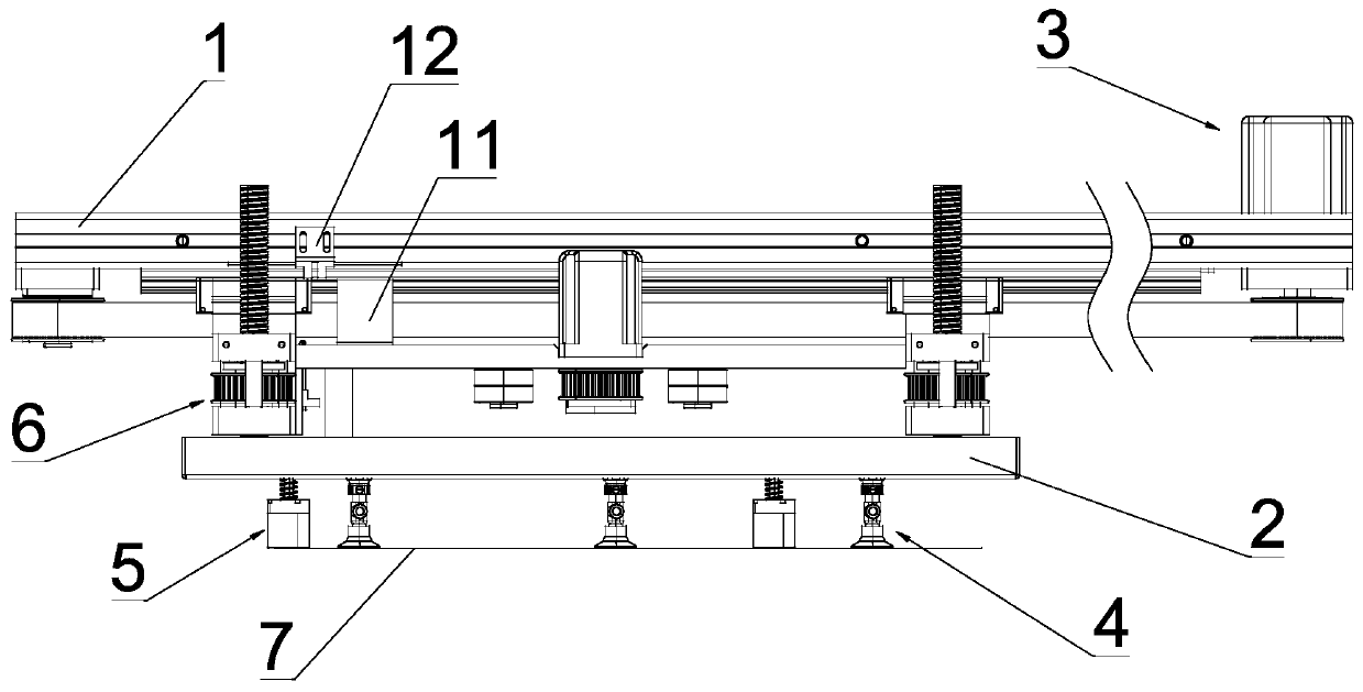
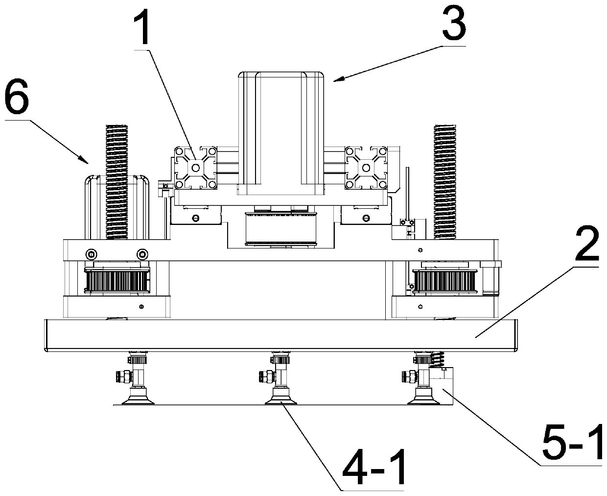
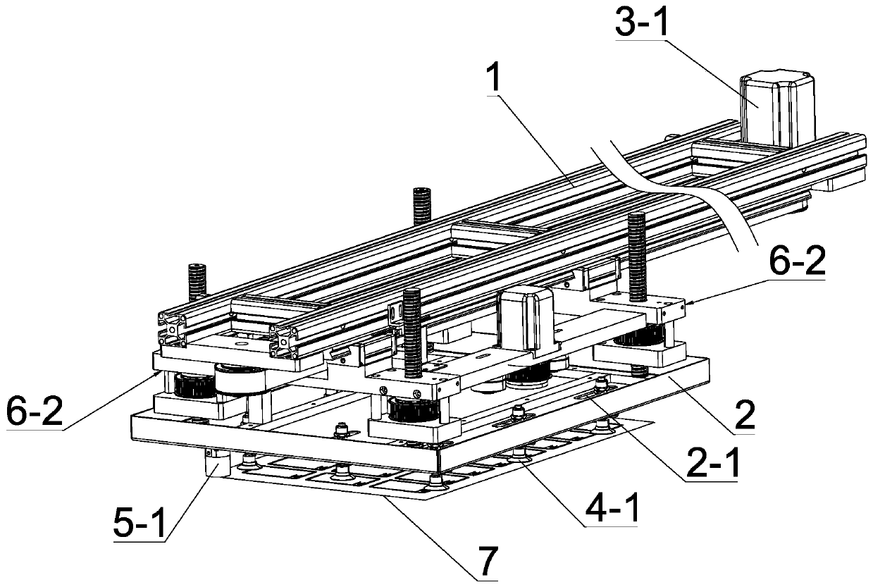
[0042] see Figure 1-Figure 6 , the sheet material positioning and conveying device of the present invention includes a frame 1, a sheet material conveying mechanism arranged on the frame 1, and drives the sheet material conveying mechanism between the pre-carrying station and the post-carrying station of the sheet material 7 A reciprocating lateral drive mechanism 3; wherein, the plate handling mechanism includes a mounting frame 2, a suction cup assembly 4 arranged on the mounting frame 2, at least two sets of positioning assemblies 5, and drives the suction cup assembly 4 and the positioning assembly 5 vertical power mechanism 6 for vertical movement; the suction cup assembly 4 includes a plurality of suction cups 4-1 for holding the sheet material 7, and the positioning assembly 5 includes a positioning hole 7-1 for the sheet material 7 Positioning part 5-1 for positioning at 1 position; the positioning part 5-1 is provided with an avoidance groove 5-11 for avoiding the po...

Embodiment 2

[0062] see Figure 12 , in this embodiment, different from Embodiment 1, the vertical drive assembly of the positioning assembly 5 can also be in another form, the vertical drive assembly includes a slide rail mechanism and the spring 5- 4; wherein the slider slide rail mechanism includes a positioning guide rail 5-5 and a positioning slider 5-6 matched with the positioning guide rail 5-5; the upper end of the guide rail and the mounting frame 2 connection, the positioning piece 5-1 is fixed on the lower end of the positioning slider 5-6 through the connecting piece 5-7, and the lower part of the positioning guide rail 5-5 is also provided for limiting the positioning slider 5 - the limiting part 5-21 at position 6, the spring 5-4 is arranged between the installation frame 2 and the positioning slider 5-6, one end of the spring 5-4 acts on the frame 1, One end acts on the positioning slider 5-6. Through the slide rail mechanism, the stability of the positioning member 5-1 du...

Embodiment 3

[0064] see Figure 13 , the difference from Embodiments 1 and 2 is that the vertical power mechanism 6 can be in another form, the screw drive assembly is a group, and the first driven drive wheel 6-6 is arranged on the On the vertical fixing seat 6-2, a guide post guide sleeve mechanism for guiding the installation frame 2 to move up and down is provided between the installation frame 2 and the vertical fix seat 6-2, wherein the guide post guide sleeve mechanism is Multiple groups, the multiple sets of guide post and guide sleeve mechanisms are distributed around the mounting frame 2; each set of guide post and guide sleeve mechanisms includes guide posts 6-9 and guide sleeves 6-9 that cooperate with the guide posts 6-9 10. One end of the guide sleeve 6-10 is fixed on the vertical fixing base 6-2, one end of the guide post 6-9 is fixed on the installation frame 2, and the other end extends vertically upwards and passes through the guide Set 6-10; the screw rod 6-3 of the scr...


PUM


Abstract

The invention discloses a board locating and carrying device comprising a machine frame, a board carrying mechanism arranged on the machine frame and a transverse driving mechanism driving the board carrying mechanism to move. The board carrying mechanism comprises an installation frame, a suction cup assembly arranged on the installation frame, at least two locating assemblies and a vertical power mechanism driving the suction cup assembly and the locating assemblies to conduct vertical movement. The suction cup assembly comprises multiple suction cups. Each locating assembly comprises a locating piece used for locating a locating hole portion of a board. Each locating piece is provided with a receding groove used for avoiding a locating pin, penetrating through the locating hole, on theboard holding platform. The bottom face of each locating piece is further provided with suction holes used for sucking the portion, around the locating hole, of the board. The board locating and carrying device is adopted before smart card machining and manufacturing and accurately locates the board used as the raw material in the carrying process, so that locating of the board on the two stationsbefore and after carrying is accurate, and the product yield is improved.

Description

technical field [0001] The invention relates to a non-contact smart card manufacturing equipment, in particular to a sheet material positioning and conveying device. Background technique [0002] With the development of contactless smart card technology, the requirements for the production and processing of smart cards are getting higher and higher. In the manufacturing process of contactless smart cards, a rectangular coil is wound on the sheet material first, then the chip is welded on the antenna of the coil and packaged, and finally another layer of sheet material is covered on the packaged layer to ensure that the coil And the chip will not be exposed. Under normal circumstances, in the manufacturing process of non-contact energy cards, the premise is that the accuracy of the placement position must be accurate during the sheet material handling and transportation process, otherwise it will affect a series of subsequent problems, such as reducing the accuracy of windin...

Claims


Application Information

Patent Timeline
IPC IPC(8): B65G47/90
CPCB65G47/901
Inventor 王开来赖汉进卢国柱吴伟文
Owner 广州明森合兴科技有限公司
Why Eureka
Try Eureka