
A protective fixing device for hoisting glass used in buildings

A fixed device and construction technology, applied in safety devices, transportation and packaging, load hanging components, etc., can solve problems such as inability to use elevators, glass breakage, glass application, etc., to achieve convenient and quick installation and disassembly, and increase internal and external pressure. Poor, the effect of increasing the contact area

Active Publication Date: 2021-03-16
奉节县华东建筑工程有限责任公司
View PDF4 Cites 0 Cited by
  • Summary
  • Abstract
  • Description
  • Claims
  • Application Information

AI Technical Summary

Problems solved by technology

[0003] However, when replacing larger glass in areas with higher floors after construction, elevators cannot be used to carry it. When using suction cups and pull ropes to lift the glass, when the floor is higher, due to the weather, it is easy to The glass swings back and forth, and the pullers at the bottom cannot exert a greater force on the glass away from the building, making it easy for the glass to touch the building. When the glass is in contact with the wall, it is easy to cause scratches on the glass, or even directly break the glass , At the same time, the shaking range of the glass is too large, it is easy to cause uneven force on the suction cup, and the air enters the interior of the suction cup, which affects the firmness of the suction cup and the glass. At the same time, the drawstring and the suction cup are directly fixed by binding, which is not fast enough , and the disassembly between the drawstring and the suction cup is not convenient and quick

Method used


Image

  • A protective fixing device for hoisting glass used in buildings
  • A protective fixing device for hoisting glass used in buildings
  • A protective fixing device for hoisting glass used in buildings

Examples


Embodiment Construction

[0025] In order to make the technical means, creative features, goals and effects achieved by the present invention easy to understand, the present invention will be further described below in conjunction with specific embodiments.

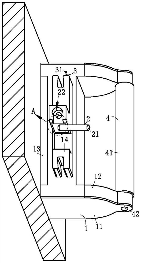
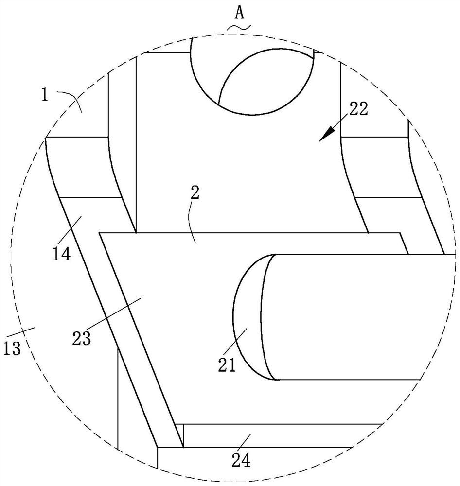
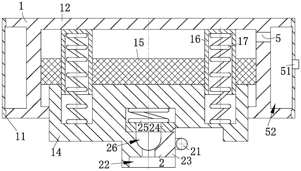
[0026] Such as Figure 1-Figure 6 As shown, a protective and fixing device for hoisting glass in buildings according to the present invention includes a fixing structure 1, a lifting structure 2, a position limiting structure 3, a guiding structure 4 and a pressure reducing structure 5; The lifting structure 2 is provided on the fixed structure 1, and the lifting structure 2 used to fix the pull cord is detachably connected to the fixed structure 1; The guide structure 4 is transported, and the guide structure 4 is rotationally connected with the fixed structure 1; one end of the fixed structure 1 is provided with the limit structure for limiting the guide structure 4 3. The limiting structure 3 is engaged with the guiding structure 4; the other ...


PUM


Abstract

The invention relates to the field of glass hoisting equipment, in particular to a protective fixing device for hoisting glass for a building. The protective fixing device comprises a fixing structure, a lifting structure, a limiting structure, guide structures and a depressurization structure, wherein the fixing structure is arranged, and can be quickly mounted and fixed on the side surface of glass; when the fixing structure is matched with the lifting structure for quickly lifting glass, a gas accommodating cavity inside the fixing structure is greater through gravity of the glass, so thatinternal and external pressure intensity difference of the fixing structure is further increased, and the fixing structure is connected to glass more firmly, and therefore, the fixing structure and the glass are mounted and dismounted more conveniently and quickly; and the guide structures are rotatably connected to the fixing structure, and a pull rope at the top end and a pull rope at the lowerend are matched with glass to define a trapezoid, and multiple guide structures on the glass and a wall body are lifted in a rolling mode, so that glass lifting is more stable, and glass is preventedfrom hitting against the wall body due to wind effects in a lifting process, and therefore, glass lifting efficiency and glass quality are higher.

Description

technical field [0001] The invention relates to the field of glass hoisting equipment, in particular to a protective and fixing device for hoisting glass used in buildings. Background technique [0002] Glass is an amorphous inorganic non-metallic material, generally made of various inorganic minerals (such as quartz sand, borax, boric acid, barite, barium carbonate, limestone, feldspar, soda ash, etc.) It is widely used in buildings, used for wind and light transmission, and is a mixture. There are also colored glass that is mixed with certain metal oxides or salts to show color. It is used to replace broken large glass in areas with higher floors. For bulky glass, suction cups and pull ropes are often used to lift the glass. [0003] However, when replacing larger glass in areas with higher floors after construction, elevators cannot be used to carry it. When using suction cups and pull ropes to lift the glass, when the floor is higher, due to the weather, it is easy to ...

Claims


Application Information

Patent Timeline
Patent Type & Authority Patents(China)
IPC IPC(8): B66C15/00
CPCB66C15/00
Inventor 不公告发明人
Owner 奉节县华东建筑工程有限责任公司
Learn More