Liquid-phase discharge shock wave drilling device

A liquid phase discharge and shock wave technology, which is used in liquid/gas jet drilling, drilling equipment, directional drilling, etc., can solve the problems of short life, low energy transmission, conversion, distribution and utilization efficiency, poor life and stability, etc. , to achieve the effect of simple operation, improved bottom hole flow field and low cost

Inactive Publication Date: 2019-12-10
CHINA UNIV OF PETROLEUM (BEIJING)
View PDF6 Cites 4 Cited by
  • Summary
  • Abstract
  • Description
  • Claims
  • Application Information

AI Technical Summary

Problems solved by technology

[0005] Traditional drilling methods have always had problems such as low efficiency in energy transmission, conversion, distribution and utilization during the drilling process
Although rotary percussion drilling and downhole pressurized drilling can increase the ROP to varying degrees, they have not been widely used in the field due to their poor life and stability.
Pulse jet assisted drilling technology has achieved certain results in the field, but because of its short life, there are also certain limitations

Method used


Image

  • Liquid-phase discharge shock wave drilling device
  • Liquid-phase discharge shock wave drilling device
  • Liquid-phase discharge shock wave drilling device

Examples


Embodiment Construction

[0034] The details of the present invention can be understood more clearly with reference to the accompanying drawings and the description of specific embodiments of the present invention. However, the specific embodiments of the present invention described here are only for the purpose of explaining the present invention, and should not be construed as limiting the present invention in any way. Under the teaching of the present invention, the skilled person can conceive any possible modification based on the present invention, and these should be regarded as belonging to the scope of the present invention. It should be noted that when an element is referred to as being “disposed on” another element, it may be directly on the other element or there may also be an intervening element. When an element is referred to as being "connected to" another element, it can be directly connected to the other element or intervening elements may also be present. The terms "mounted", "connec...


PUM


Abstract

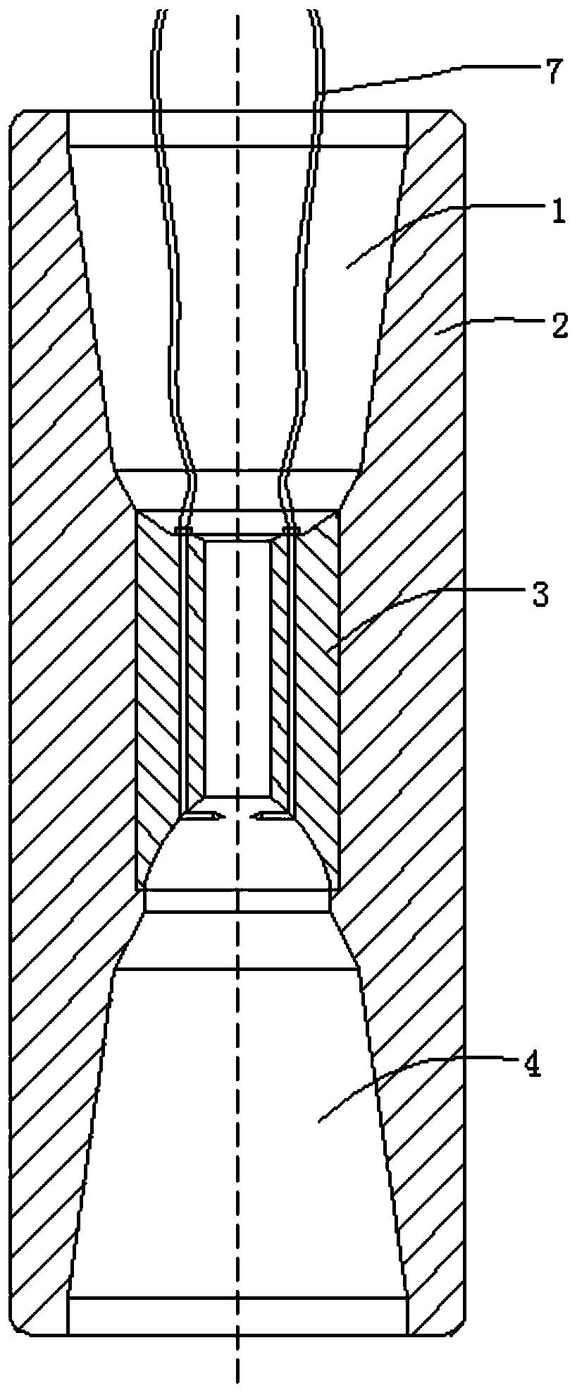
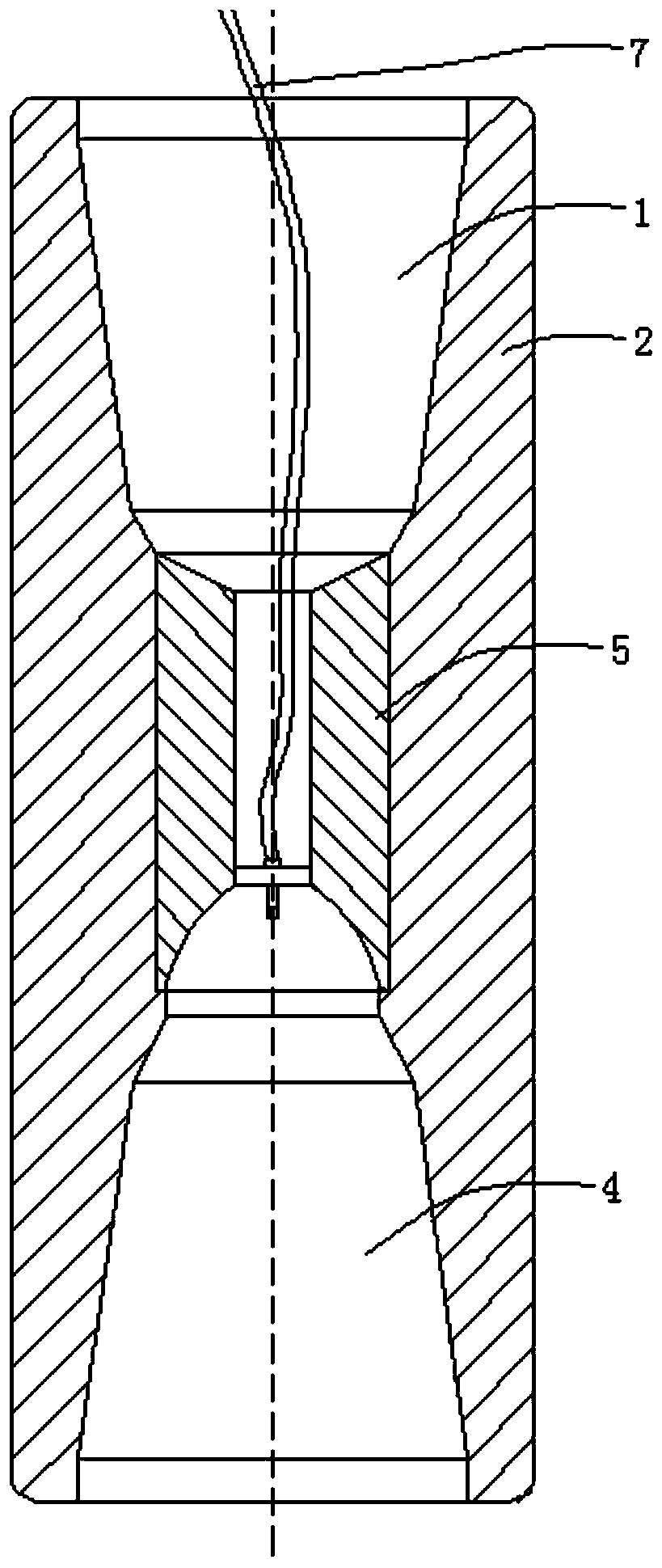
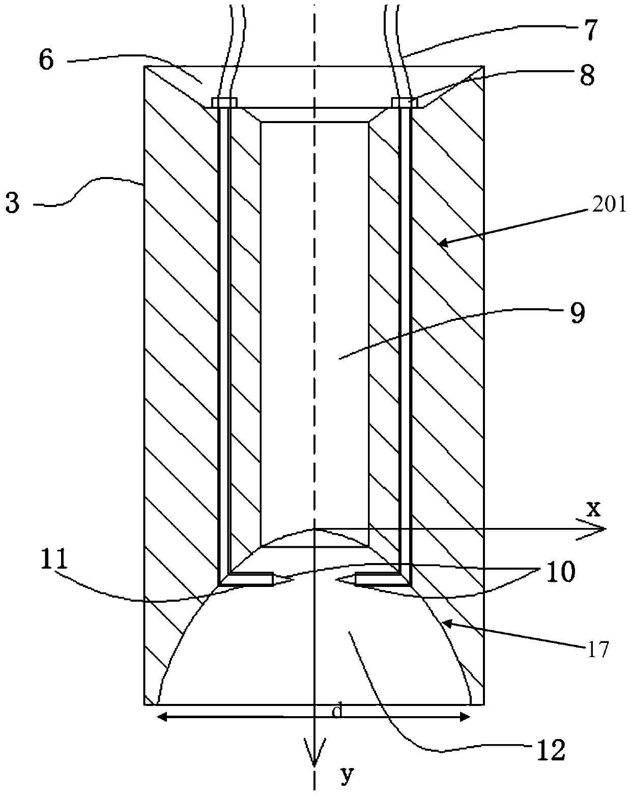
The invention discloses a liquid-phase discharge shock wave drilling device. The device comprises a shell provided with a fluid inlet section and a fluid outlet section, wherein a liquid-electricity pulse generator is arranged in the shell, and comprises a hollow body, a central flowing channel is formed in the middle of the body, a diversion opening is formed in the upper part of the body, a fluid outlet, a first electrode and a second electrode are formed at the lower part of the body, an electrode gap is formed between the two electrodes, the middle point of the electrode gap is located right below the central flowing channel, a rotary parabolic cavity is formed at the fluid outlet, a rotary parabolic cavity cross section parabola is formed in the section of the rotary parabolic cavity,and a parabolic vertex serves as an origin, the central axis of the shell serves as a y axis, the line which is perpendicular to the central axis of the shell serves as an x axis, the parabolic equation is that y equals a*2, wherein a is a constant. According to the device, the rock breaking can be assisted, and the drilling cost is saved.

Description

technical field [0001] The invention relates to the technical field of drilling auxiliary equipment, in particular to a liquid phase discharge shock wave drilling device. Background technique [0002] The statements in this section only provide background information related to the present disclosure and may not constitute prior art. [0003] The object of drilling and production technology is the downhole system (from the wellbore to the formation). This object is characterized by small boreholes, deep formations, complex downhole conditions, and poor visibility. Only downhole drilling and production tools can be the closest to work. object. Therefore, if you want to use the new drilling and production technology to perform fine operations on the downhole system, you can only rely on downhole drilling and production tools. [0004] The demand for the development of advanced drilling and production technology has led to the emergence of new downhole drilling and production...

Claims


Application Information

Patent Timeline
Patent Type & Authority Applications(China)
IPC IPC(8): E21B7/00E21B7/18E21B7/04
CPCE21B7/00E21B7/04E21B7/18
Inventor 张辉余庆李军蔡志翔刘科柔
Owner CHINA UNIV OF PETROLEUM (BEIJING)
Why Eureka
Try Eureka