
Two-purpose generator rotor and experimental device thereof

A generator rotor, dual-purpose technology, applied in educational appliances, instruments, teaching models, etc., can solve the problems of complex structure, complex design, difficult motor principle, etc., to achieve clear principles, simple structure design, and meet teaching requirements. Effect

Inactive Publication Date: 2019-12-10
上海宽射科技有限公司
View PDF10 Cites 0 Cited by
  • Summary
  • Abstract
  • Description
  • Claims
  • Application Information

AI Technical Summary

Problems solved by technology

In the teaching experiment of motor principles in schools, the traditional experimental equipment is mostly finished motors or disassembled parts of finished motors, which brings a lot of inconvenience to the teaching of the internal structure and principles of motors
The integrated motor is packaged in the motor casing because of various components (including rotor, stator, iron core, carbon brush, etc.), it is difficult for beginners to understand the internal winding method and the connection between various components Wire mode, so that beginners do not have a deep understanding of the principle of the motor
It is difficult to really grasp the knowledge of the principle of the motor
[0003] At present, most of the patents related to the teaching of generator experimental principles are relatively complicated in design, and the principle of AC and DC power generation is not clearly displayed. It can generate both AC and DC power
However, this patent is connected through terminal posts, and a transparent cover is installed above the base of the experimental device, which will cause users and readers to be confused about the principle of how to generate AC and DC power in this patent.
Another example is the invention patent with the publication number CN106023769A: a teaching demonstration model of a motor and a generator in one, which can also generate AC and DC power, but the structure of its design is complicated

Method used


Image

  • Two-purpose generator rotor and experimental device thereof
  • Two-purpose generator rotor and experimental device thereof
  • Two-purpose generator rotor and experimental device thereof

Examples


Embodiment Construction

[0024] Below in conjunction with accompanying drawing, technical scheme of the present invention is described in further detail:

[0025] In order to thoroughly understand the design of the present invention, detailed steps and detailed structures will be provided in the following description, so as to explain the technical solution of the present invention. Preferred embodiments of the present invention are described in detail below, however, the present invention may have other embodiments besides these detailed descriptions.

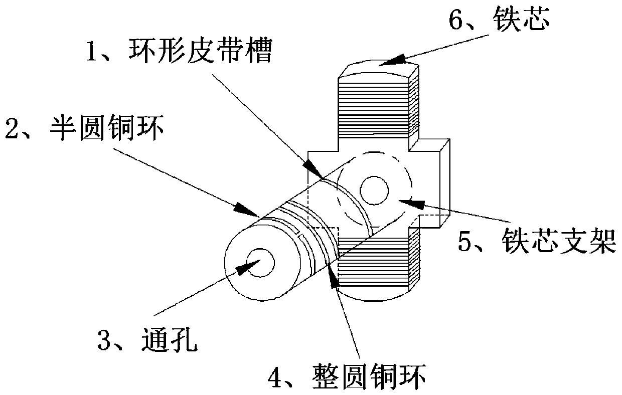
[0026] A dual-purpose generator rotor, such as figure 1 As shown, it includes an iron core 6, an iron core support 5, an endless belt groove 1, copper wires, two semicircular copper rings 2, two full-circle copper rings 4 and through holes 3, etc.

[0027] Among them, it is necessary to fix all the copper rings on the iron core bracket, such as figure 1 Fix the ring at positions 2 and 4 shown in . It should be noted that two semi-circular copper ri...


PUM


Abstract

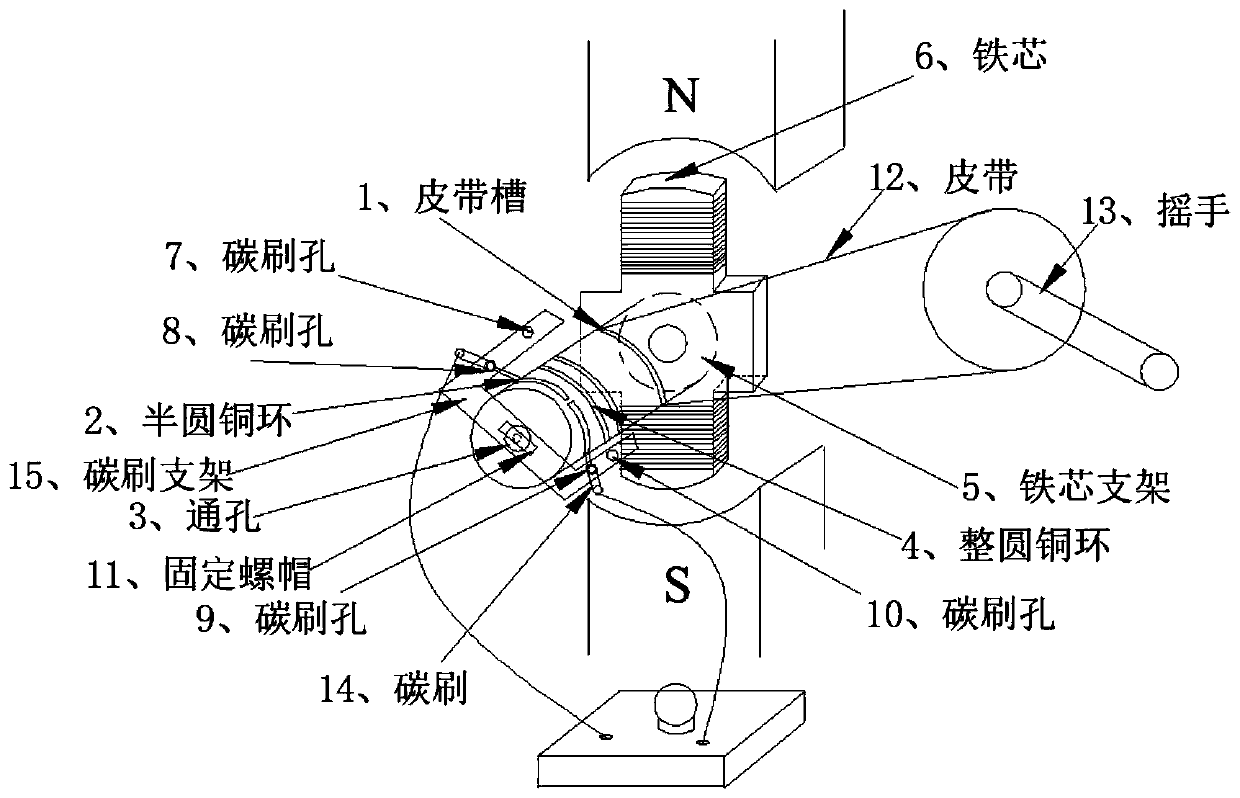
The invention discloses a two-purpose generator rotor and an experimental device thereof, and relates to the field of structural design of generator rotors and the field of motor experimental principle teaching. The two-purpose generator rotor comprises a pair of anisotropic permanent magnets, a carbon brush support, a carbon brush, a belt, a handle, a bulb, a fixing screw cap, an iron core, an iron core support, an annular belt groove, a copper wire, two semicircular copper rings, two circular copper rings, a base and the like. The main design idea of the two-purpose generator rotor is that atraditional generator rotor is improved, so that the designed rotor can lead out a single-phase alternating-current voltage and a direct-current voltage after magnetic induction lines are cut in a magnetic field.

Description

technical field [0001] The invention relates to the structural design of a generator rotor and the teaching field of motor experiment principles, in particular to a dual-purpose generator rotor and an experimental device thereof. Background technique [0002] As we all know, there are many types of motors on the market, and the device structure is relatively complicated, and the same is true for generators. And because motors are mostly used in industrial production, they are mostly integrated products developed by manufacturers. In the teaching experiment of motor principles in schools, the traditional experimental equipment is mostly finished motors or disassembled parts of finished motors, which brings a lot of inconvenience to the teaching of the internal structure and principles of motors. The integrated motor is packaged in the motor casing because of various components (including rotor, stator, iron core, carbon brush, etc.), it is difficult for beginners to understa...

Claims


Application Information

Patent Timeline
Patent Type & Authority Applications(China)
IPC IPC(8): G09B23/18
CPCG09B23/188
Inventor 马凯
Owner 上海宽射科技有限公司
Learn More