
Continuation device and method of optical fiber composite low-voltage cable

A low-voltage cable and optical fiber composite technology, which is applied in the connection/termination of cable equipment, optical waveguide coupling, optics, etc., can solve problems such as construction difficulties, construction quality guarantees, and optical fiber damage, and facilitate transportation and inspection. , Eliminate defects and hidden dangers, and promote the effect of infrastructure construction

Pending Publication Date: 2019-12-10
STATE GRID HUBEI ELECTRIC POWER CO XIAOGAN POWER SUPPLY CO +1
View PDF0 Cites 1 Cited by
  • Summary
  • Abstract
  • Description
  • Claims
  • Application Information

AI Technical Summary

Problems solved by technology

[0004] In order to overcome the defects of the prior art, the technical problem to be solved by the present invention is to provide a splicing device for optical fiber composite low-voltage cables, which solves the difficulties in the construction of the current OPLC cable engineering, the difficulty in guaranteeing the construction quality, and the damage to the optical fibers caused by the heating of the cable joints. It eliminates the hidden danger of defects buried by the connection, facilitates the inspection work, prevents the interruption of the optical channel caused by the fiber break caused by the cable inspection operation, and prevents the operator from electric shock caused by accidentally touching the exposed cable when inspecting the optical channel. , improve the safe operation rate of power distribution network, improve the operation rate of distribution fiber optics, ensure the safety of personnel and equipment during inspection operations, promote the application of new technologies for OPLC cables, and promote the infrastructure construction of the power ubiquitous Internet of Things

Method used


Image

  • Continuation device and method of optical fiber composite low-voltage cable
  • Continuation device and method of optical fiber composite low-voltage cable
  • Continuation device and method of optical fiber composite low-voltage cable

Examples


Embodiment Construction

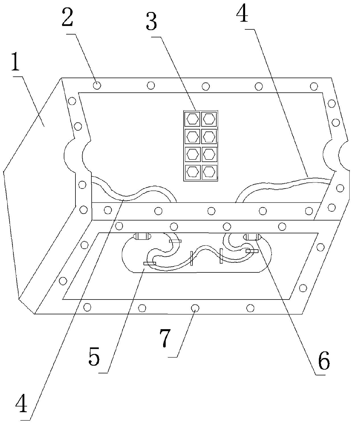
[0017] Such as figure 1 As shown, this optical fiber composite low-voltage cable connection device integrates electrical and optical connection side isolation, reduces the volume of the box body, facilitates installation and construction, and is safe and reliable for transportation and inspection. It includes: box body 1, cable terminal 3, fiber channel slot 4, splice tray 5, cover;

[0018] The cable terminal 3, the fiber channel slot 4, and the splice tray 5 are in the box body 1, and the cover is covered on the box body;

[0019] The cable separated after cutting the incoming line of the optical fiber composite low-voltage cable is connected to the left side of the cable terminal 3; the cable separated after the outgoing line of the optical fiber composite low-voltage cable is connected to the right side of the cable terminal 3;

[0020] The optical fiber composite low-voltage cable enters the separated optical fiber after cutting. After fusion splicing in the fiber fusion...


PUM


Abstract

The invention discloses a continuation device of an optical fiber composite low-voltage cable. The continuation device comprises a box body (1), a cable wiring terminal (3), an optical fiber channel groove (4), a fiber melting disc (5) and a cover. The cable wiring terminal (3), the optical fiber channel groove (4) and the fiber melting disc (5) are arranged in the box body (1), and the cover covers the box body. A cable wire separated after the optical fiber composite low-voltage cable carries out wire incoming and is cut is connected to a left side of the cable wiring terminal (3). The cablewire separated after the optical fiber composite low-voltage cable carries out wire outgoing and is cut is connected to a right side of the cable wiring terminal (3). A separated optical fiber afterthe optical fiber composite low-voltage cable carries out wire incoming and is cut penetrates into the optical fiber channel groove (4), and after the fiber melting disc (5) is welded, excess-length optical fibers are coiled into the fiber melting disc (5) according to a construction technology requirement. The invention also discloses a method.

Description

technical field [0001] The invention relates to the technical field of power distribution optical fibers, in particular to a splicing device for an optical fiber composite low-voltage cable and a splicing method for an optical fiber composite low-voltage cable. Background technique [0002] Distribution fiber optic network is the basic network of power ubiquitous Internet of Things. In order to improve the safe operation rate of distribution fiber optic network, distribution power lines have begun to promote OPLC (Optical Fiber Composite Low-voltage Cable, optical fiber composite low-voltage cable) new technology technology Application to improve the safe operation rate of power distribution fiber channel. OPLC is another optical fiber composite cable after OPGW and OPPC. Integrating optical fiber, power transmission copper wire, and copper signal wire can solve problems such as broadband access, equipment power consumption, and emergency signal transmission; through PON te...

Claims


Application Information

Patent Timeline
Patent Type & Authority Applications(China)
IPC IPC(8): H02G1/14G02B6/255
CPCH02G1/14G02B6/255
Inventor 张悦饶渝泽赵泽予付津剑江涛夏甚然张瑾孙婷周鑫叶青范伟吴世华徐雄军黄龙程建军徐少峰朱见新李芳亚徐可蒋家勇张晓华
Owner STATE GRID HUBEI ELECTRIC POWER CO XIAOGAN POWER SUPPLY CO
Learn More