
A multi-unit communication test system based on fpga

A communication test and multi-unit technology, applied in the field of network communication, can solve problems such as insufficient communication speed and insufficient number of serial ports, and achieve the effects of high test efficiency, large number of serial ports, and strong scalability

Active Publication Date: 2022-04-22
SOUTH CHINA UNIV OF TECH
View PDF4 Cites 0 Cited by
  • Summary
  • Abstract
  • Description
  • Claims
  • Application Information

AI Technical Summary

Problems solved by technology

[0004] The object of the present invention is to solve the simulation test problem of high-speed rail communication, by above-mentioned analysis, the microcomputer with CPU structure such as single-chip microcomputer has various defects, can not undertake this task well, in view of this, the present invention provides a kind of realization based on FPGA The multi-unit communication test system adopts the FPGA that can be executed in parallel instead of the single-chip microcomputer as the main control chip of the communication circuit to solve the problem of insufficient number of serial ports and insufficient communication speed. At the same time, the FPGA can be programmed and controlled by the host computer, which improves the flexibility of the system. and adaptability, human-computer interaction is also enhanced

Method used


Image

  • A multi-unit communication test system based on fpga
  • A multi-unit communication test system based on fpga
  • A multi-unit communication test system based on fpga

Examples


Embodiment

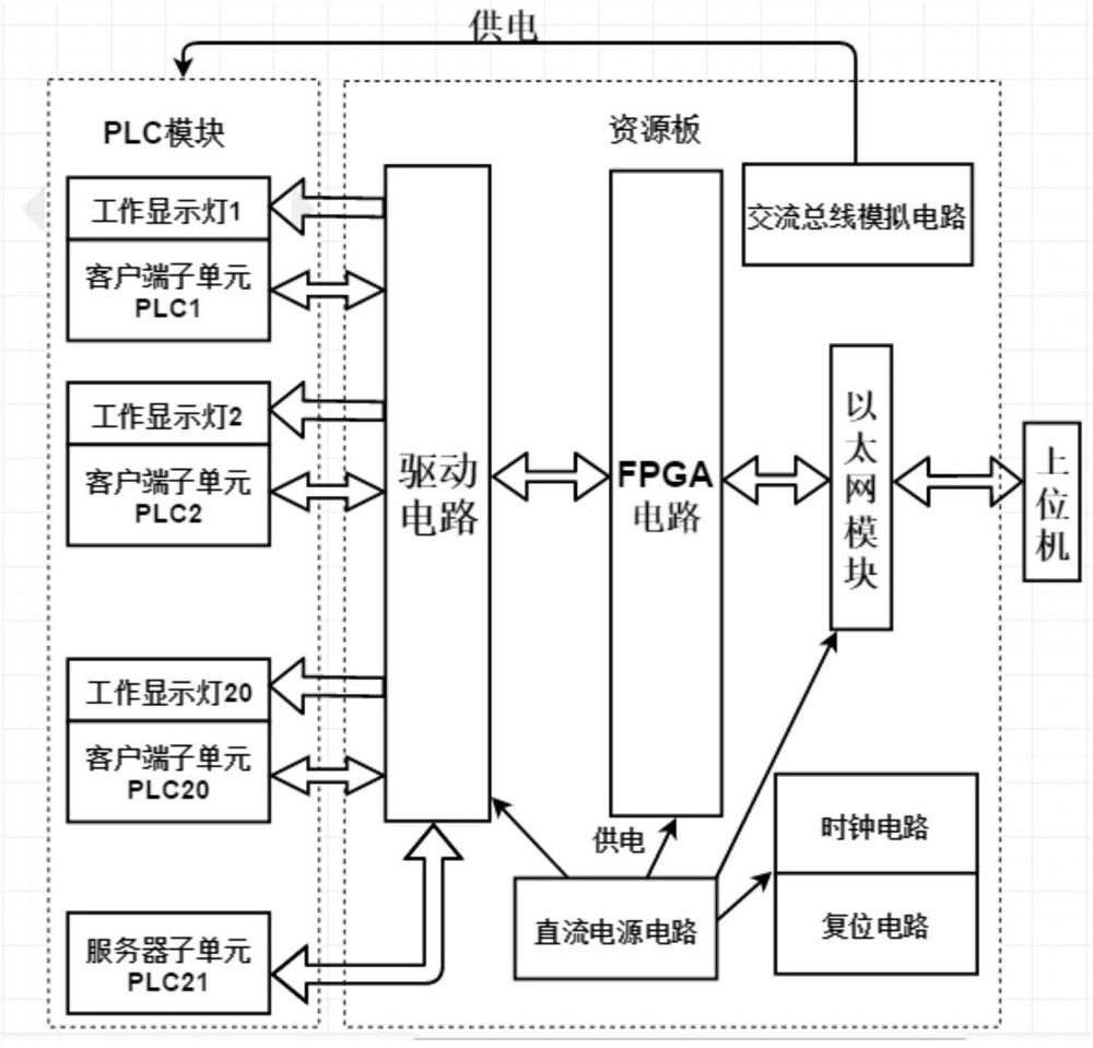
[0036] Such as figure 1 As shown, a multi-unit communication test system based on FPGA, including resource board, PLC module and host computer. The resource board mainly includes FPGA circuit, drive circuit, Ethernet module, AC bus analog circuit, DC power supply circuit, clock circuit and reset circuit; PLC module includes 20 client sub-units PLC1-PLC20, 20 working display lights LED1-LED20 , 20 switches S1-S20 and 1 server subunit PLC21, wherein one client subunit corresponds to one work display light, and both the client subunit and the server subunit belong to the PLC unit.

[0037] In the resource board, the drive circuit, the clock circuit and the reset circuit are connected to the FPGA circuit; the FPGA circuit is connected to the Ethernet module.

[0038] The client subunit PLC1-PLC20, work display lamp LED1-LED20 and server subunit PLC21 of the PLC module are connected to the drive circuit in the resource board; the TX and RX ports of each PLC unit are connected to t...


PUM


Abstract

The invention discloses a multi-unit communication test system realized based on FPGA, which includes a resource board, a PLC module and a host computer. The resource board includes FPGA circuit, drive circuit, Ethernet module, AC bus simulation circuit, DC power supply circuit, clock circuit and reset circuit; PLC module includes 20 client subunits PLC1‑PLC20, each client subunit is equipped with a working Display light LED1-LED20 and switch S1-S20, and a server subunit PLC21; the client subunit, work display light and server subunit of the PLC module are connected to the drive circuit of the resource board, and the drive circuit, clock circuit and reset circuit are connected to the FPGA circuit, the FPGA circuit is connected to the Ethernet module. The present invention has the advantages of a large number of serial ports, fast communication speed, high test efficiency and real-time programming control by the upper computer. It realizes the communication between each PLC unit and the upper computer and the PLC unit based on the FPGA chip, and realizes the maximum simulation The purpose of testing the desired communication environment.

Description

technical field [0001] The invention belongs to the technical field of network communication, and in particular relates to a structure and a method for performing data communication between various PLC units and between a host computer and a PLC unit through an FPGA chip. Background technique [0002] High-speed rail technology is a rapidly developing emerging industry. To ensure its safe and reliable operation, good data exchange communication is inseparable. Generally speaking, it is unrealistic to conduct communication tests directly on high-speed rail, and the cost is high. It is necessary to simulate the environment of high-speed rail communication through certain technical means to test the status and reliability of communication. With the development of science and technology, especially communication technology and network transmission technology, it is possible to simulate the communication of multiple carriages of high-speed rail. [0003] The traditional communic...

Claims


Application Information

Patent Timeline
Patent Type & Authority Patents(China)
IPC IPC(8): H04L43/50H04L41/14H04B17/391
CPCH04L43/50H04L41/145H04B17/3912
Inventor 胡帅邱磊鑫陈杰隆陶薮元刘建业刘晓瑛
Owner SOUTH CHINA UNIV OF TECH
Learn More