[0058] The technical solutions of the present invention will be further described in detail below through the accompanying drawings and embodiments. Although exemplary embodiments of the present disclosure are shown in the drawings, it should be understood that the present disclosure can be implemented in various forms and should not be limited by the embodiments set forth herein. On the contrary, these embodiments are provided to enable a more thorough understanding of the present disclosure and to fully convey the scope of the present disclosure to those skilled in the art.
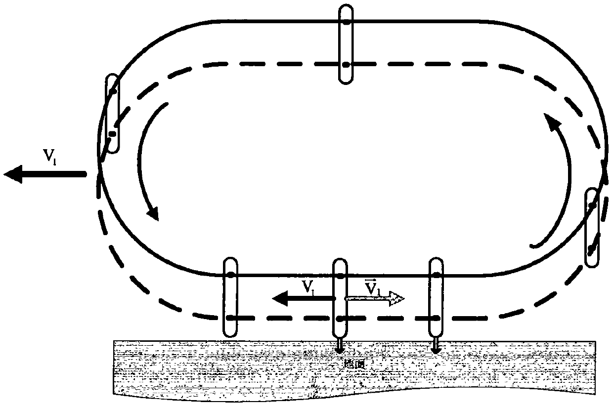
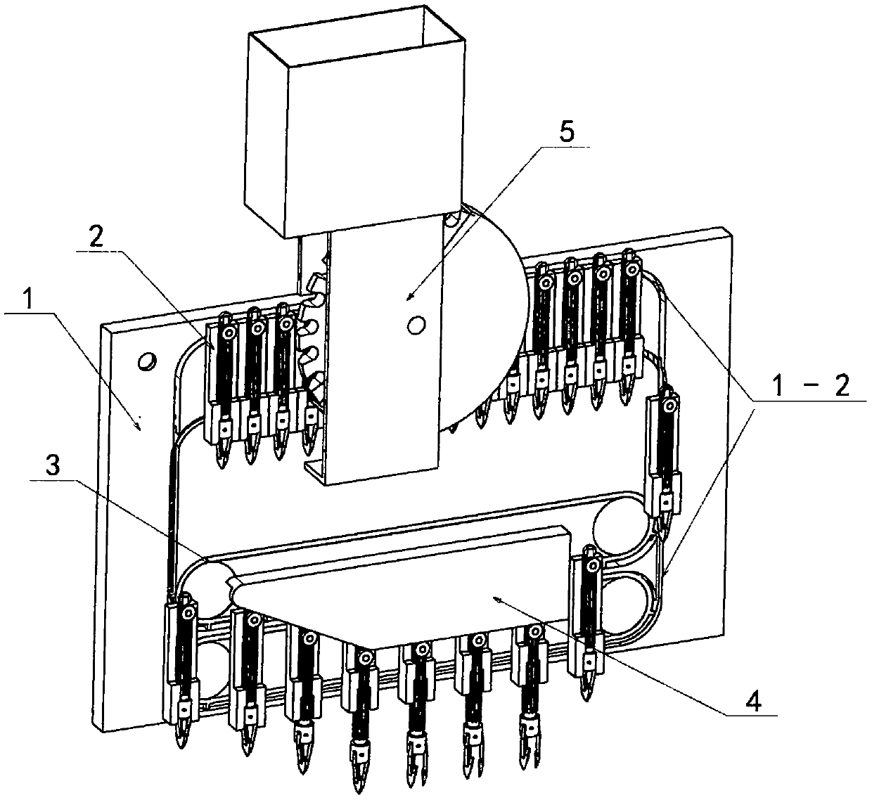
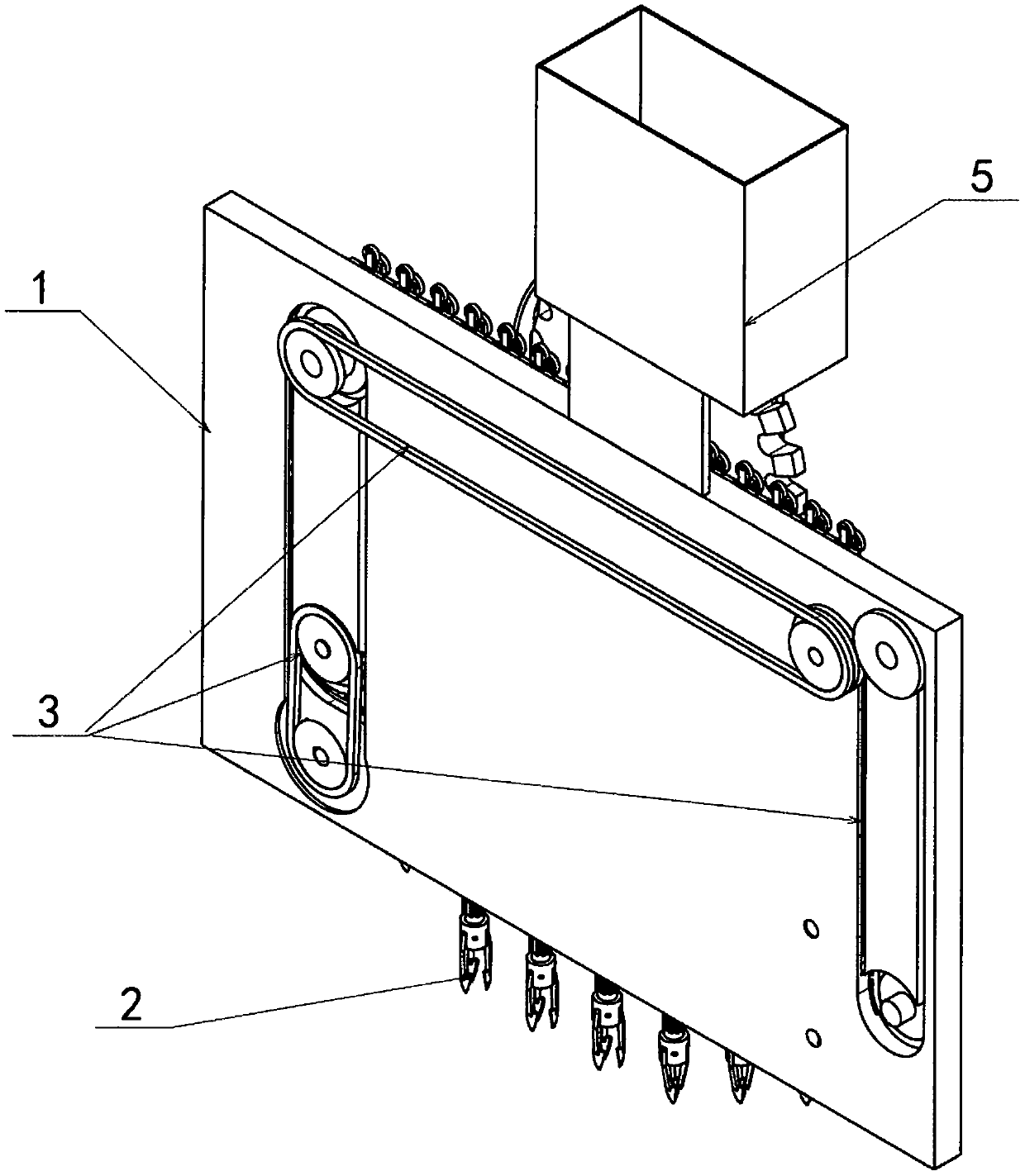
[0059] Such as Figure 2 to Figure 26 As shown, the technical solution adopted by the present invention is: a seeding device, including a guide rail rack 1 provided with a guide rail 1-2, a plurality of discrete interspersion transfer mechanisms that cooperate with the guide rail 1-2, and installation A transfer drive mechanism 3 on the rail frame 1 that drives the interleaved transfer mechanism 2 to move along the guide rail 1-2, is installed on the rail frame 2 and cooperates with the interleaved transfer mechanism 2 to release the interleaved actuator for planting crops 4.
[0060] The guide rail rack 1 of the present invention includes a rack 1-1, a first guide rail 1-21 and a second guide rail 1-22 that are parallel to each other and offset a certain distance on the rack 1-1. 1-1 is also provided with a number of holes or slots 1-3 for the installation of the transport drive mechanism 3, wherein the geometric shapes of the first guide rail 1-21 and the second guide rail 1-22 are completely the same or partially the same.
[0061] Such as figure 2 As shown, as a preferred solution of the present invention, the rail rack 1 is a single-sided rack, the rack 1-1 is a single plate-shaped structure, and the first rail 1-21 and the second rail 1-22 They are arranged on the same side of the rack 1-1, and there is no space between the first guide rail 1-21 and the second guide rail 1-22 for the insertion and transfer mechanism to move.
[0062] As shown in the figure, as another preferred solution of the present invention, the guide rail rack 1 is a double-sided rack, and its rack 1-1 includes a left rack 1-11 and a right rack 1-12. Between the rack 1-11 and the right rack 1-12, there is a space for the insertion transfer mechanism 2 to move. The left rack 1-11 is provided with a first guide rail 1-21, and the right rack 1-12 is provided with a Two guide rails 1-22.
[0063] Such as Figure 5 to Figure 13 As shown, as a preferred solution of the present invention, the rack rail 1 has the first rail 1-21 and the second rail 1-22 on the rack rail 1 offset by a certain distance in the vertical direction.
[0064] The guide rail 1-2 of the present invention is a mechanism that enables the interstitial transfer mechanism 2 to move smoothly along the guide rail 1-2 to return to the initial position. The center line of the guide rail 1-2 has a closed curve, such as a parallelogram, An oblong, triangle, ellipse, circle, chord, rectangle, square, trapezoid, polygon, closed free-form curve, or a closed curve with a combination of some line segments. When the bottom of the guide rail 1-2 contains a straight line, the transfer drive mechanism 3 can make the interstitial transfer mechanism 2 move along the guide rail 1-2 at a linear speed equal to and opposite to the forward speed of the guide rail frame 1, that is, relative to the ground. The time is long enough to provide enough time for complex planting agronomy, and the planting effect is the best.
[0065] As a preferred solution of the present invention, the guide rail 1-2 is a T-shaped groove 1-2a.
[0066] The interplanting transfer mechanism 2 of the present invention enables the planted crops to be sequentially transported from the feeding place to the interplanting mechanism at the set planting position, and during the movement, the planted crops are protected to avoid damage.
[0067] As a preferred solution of the present invention, the insertion transfer mechanism 2 includes: an insertion sleeve 2-1, an insertion punch 2-2 installed in the insertion sleeve 2-1, and an insertion sleeve 2-1. A reset mechanism 2-3 between the insertion punch 2-2 and the insertion punch 2-2. The inserting sleeve 2-1 includes a sleeve 2-11, an upper sleeve shaft 2-111 and a lower sleeve shaft 2-112 fixedly mounted on the sleeve 2-11 and parallel to each other. The limit mechanism 2-12 on the barrel shaft 2-111 and the lower sleeve shaft 2-112 cooperates with the guide rail 1-2. The insertion punch 2-2 includes an insertion rod 2-21, an insertion punch seat 2-22, an insertion finger 2-23, a pin 2-24, an insertion finger opening and closing control mechanism 2-25, and a dust cover 2-26 , The insertion rod 2-21 is installed in the insertion sleeve 2-1, the upper end of the insertion rod 2-21 is provided with a roller 2-211 that pushes the insertion rod 2-21 up and down, and the lower end of the insertion rod 2-21 is equipped with an insertion punch Head base 2-22; the insertion punch base 2-22 is provided with a number of holes or installation grooves; the insertion fingers 2-23 are installed in the insertion punch base 2-22 installation grooves through the pins 2-24, and the insertion The finger ends of fingers 2-23 are arrow-shaped. There are multiple insertion fingers 2-23 on the same insertion punch seat 2-22. After multiple insertion fingers 2-23 are closed, a common funnel-shaped space 2-23a is formed inside. A common pointed punch tip 2-23b is formed on the outside of the inserting fingers, and a gap 2-23c is reserved between two adjacent inserting fingers 2-23 near the inserting punch seat for soil to enter the funnel-shaped space; the inserting fingers The opening and closing control mechanism 2-25 is a mechanism that controls the simultaneous opening and closing of the inserting fingers 2-23 on the same inserting punch seat 2-22; the dust cover 2-26 is installed at the lower end of the inserting punch seat 2-22, The dust cover 2-26 is provided with through holes for inserting fingers 2-23 to pass through.
[0068] As a preferred solution of the present invention, the limiting mechanism 2-12 is a roller 2-121.
[0069] As another preferred solution of the present invention, the limiting mechanism 2-12 is a slider 2-122.
[0070] In the insertion sleeve 2-1 of the present invention, the upper sleeve shaft 2-111 is matched with the first guide rail 1-21 on the guide rail frame 1 through the limiting mechanism 2-12, and the lower sleeve shaft 2- 112 Cooperate with the second guide rail 1-22 of the guide rail frame 1 through the stop mechanism 2-12, and the stop mechanism 2-12 restricts the insertion sleeve 2-1 from extending the upper sleeve shaft 2-111 or the lower sleeve shaft Move in the axial direction of 2-112, so that the insertion sleeve 2-1 can only move along the guide rail 1-2; wherein all the upper sleeve shafts 2-111 installed in the first guide rail 1-21 are independent of each other, All the lower sleeve shafts 2-112 installed in the second guide rail 1-22 are also independent of each other, that is, the distance between each other on the center line of the guide rail 1-2 is not fixed, so that the insertion sleeve The tube 2-1 is in a discrete state, that is, all the inter-seed transfer mechanisms 2 are installed on the guide rails 1-2 in turn in isolation from each other, and the linear velocity of the movement on the guide rails 1-2 is variable, and the moving speed changes Change the distance between each other to avoid interference. In the process of planting into the soil, the interplanting transfer mechanism 2 sets the distance between neighbors according to the agronomic requirements of the crops to be planted. For example, when a single crop is planted, the distance between two adjacent interplanting transfer mechanisms 2 is equal to make the planting distance even; When multiple crops are planted together, such as corn and soybeans are planted alternately in the same ridge, the distance between two adjacent interplanting transfer mechanisms 2 varies due to different agronomic requirements, so that the plant spacing is equal or unequal.
[0071] As a preferred solution of the present invention, the insertion sleeve 2-1 is provided with an opening 2-1a for planting crop seedlings to enter and exit.
[0072] As a preferred solution of the present invention, the insertion rod 2-21 is a spline type, so that it can only move up and down along the axis in the insertion sleeve 2-1, and cannot rotate.
[0073] The transport drive mechanism 3 of the present invention is a mechanism that drives the inter-seed transport mechanism 2 to move along the guide rail 1-2, and can change the moving speed of the inter-seed transport mechanism 2 on the guide rail 1-2 as required. After the planted crops enter the insertion transfer mechanism 2, the transfer drive mechanism 3 quickly moves the insertion transfer mechanism 2 to the starting position of planting into the soil, and expands the distance between adjacent insertion transfer mechanisms 2 to avoid spatial interference; during the process of planting into the soil, transfer The driving mechanism 3 drives the interstitial transfer mechanism 2 to move relative to the rail frame 1 at a linear speed that is opposite to the moving speed of the rail frame 1 relative to the ground, and the difference is within a set range. According to the physical principle of relative motion, that is, interstitial transfer The moving speed of mechanism 2 relative to the ground is within the set value range. This is because of manufacturing errors or assembly errors. In reality, it is difficult to ensure that the interplanting transfer mechanism 2 is absolutely stationary relative to the ground. It is set on the premise of meeting the requirements of planting and agronomy. The error tolerance range, but during the planting process, the lower the moving speed of the interplant transfer mechanism 2 relative to the ground, the better. When the interplant transfer mechanism 2 is absolutely stationary with respect to the ground, the planting process is ideal and the effect is the best; after planting, the transfer drive is driven The mechanism 3 makes the inter-cut transfer mechanism 2 leave the ground quickly to avoid space interference.
[0074] As a preferred solution of the present invention, the transfer drive mechanism 3 is embedded in the guide rail frame 2 and at least includes a feeding drive mechanism 3-1, a planting soil drive mechanism 3-2, and a return drive mechanism that are related to each other. 3-3, and several intermediate transmission mechanisms 3-6 connecting the feeding drive mechanism 3-1, the planting soil drive mechanism 3-2, and the return drive mechanism 3-3. The feeding drive mechanism 3-1 includes a feeding driving wheel 3-11, a feeding driven wheel 3-12 installed on the guide rail frame 2, and a driving wheel 3-11 and a driven wheel 3-12. The feeding flexible driving mechanism 3-13 is matched with the inserting sleeve 2-1; the planting soil driving mechanism 3-2 includes the upper driving wheel 3-21, the upper driven wheel 3-22, and the installation Between the upper driving wheel 3-21 and the upper driven wheel 3-22, the upper flexible drive mechanism 3-23, the lower driving wheel 3-24, and the lower driven wheel 3-25, which are matched with the upper sleeve shaft 2-111, are installed Between the lower driving wheel 3-24 and the lower driven wheel 3-25, the planting lower flexible driving mechanism 3-26 is matched with the lower quill 2-112; the return driving mechanism 3-3 includes a mounting on the guide rail frame 1 A return driving wheel 3-31, a return driven wheel 3-32, and a return flexible drive mechanism 3-33 installed between the driving wheel 3-31 and the driven wheel 3-32 to cooperate with the insertion sleeve 2-1.
[0075] As a further preferred solution of the present invention, the flexible driving mechanism 3-13 or 3-23 or 3-33 includes a chain 3-4 and a stop 3-5 installed on the chain 3-4.
[0076] The inter-planting execution mechanism 4 of the present invention is a mechanism that cooperates with the inter-planting transfer mechanism 2 so that the inter-planting transfer mechanism 2 sequentially releases crops for planting at a set position.
[0077] As a preferred solution of the present invention, the interstitial execution mechanism 4 includes a mounting plate 4-1 matched with the interstitial rack 2-2, and a fixed installation on the mounting plate 4-1 to push the interstitial head 2-2 into the device. The cut-in depth control slide plate 4-11 with fixed depth of soil, the cut-in finger opening and closing slide plate 4-12 that is fixedly installed on the mounting plate 4-1 and cooperates with the cut-in finger opening and closing control mechanism 2-25.
[0078] As another preferred solution of the present invention, the interruption actuator 4 includes an interruption actuator 4-21 installed on the insertion frame, and an interruption punch 2-2 installed on the insertion actuator 4-21. Push in the insertion press plate 4-22 of the setting soil, the opening and closing actuator 4-23 that is installed on the insertion press plate 4-22 to open and close the insertion finger 2-23, and the opening and closing cylinder 4-23. The opening and closing pressure plate 4-24. The inter-cut actuator 4-21 or the opening and closing actuator 4-23 is a controllable telescopic mechanism.
[0079] A planter adopting the seeding device of the present invention includes a power locomotive 6, a frame 6 installed on the power locomotive 6, a plurality of the planting devices installed on the frame 6, and the seeding transfer mechanism 2 A feeding device 5 for planting crops, a transmission device 8 installed on the frame 7 to cooperate with the transfer driving mechanism 3, and an auxiliary device 9 for the seeding device are provided in cooperation.
[0080] The feeding device 7 of the present invention is a device that picks and preprocesses interplanting crops, and cooperates with the interplanting transfer mechanism 2 to order the planted crops into the interplanting transfer mechanism 2.
[0081] The auxiliary device 9 of the present invention is a device that completes one or more of fertilization, watering, spraying, mulching, perforating or other auxiliary planting operations.
[0082] The above examples are only used to explain the content claimed by the present invention, but are not used to limit the scope of the present invention. The position change or combination of the components in the above examples by those skilled in the art belongs to the protection scope of the present invention; the improvements and substitutions made by those skilled in the art within the scope of the present invention belong to the protection scope of the present invention.