A positioning and bending device for steel bars for construction engineering

A construction engineering and bending device technology, which is applied in the field of steel bar positioning and bending devices for construction engineering, can solve problems such as low efficiency, and achieve the effects of ensuring bending effect, improving cutting efficiency, and ensuring stability

Active Publication Date: 2020-07-31
安徽省天之泽工程科技有限公司
View PDF7 Cites 0 Cited by
  • Summary
  • Abstract
  • Description
  • Claims
  • Application Information

AI Technical Summary

Problems solved by technology

[0005] The purpose of the present invention is to solve the problem of low efficiency in the prior art, and propose a positioning and bending device for steel bars used in construction engineering

Method used


Image

  • A positioning and bending device for steel bars for construction engineering
  • A positioning and bending device for steel bars for construction engineering
  • A positioning and bending device for steel bars for construction engineering

Examples


Embodiment 1

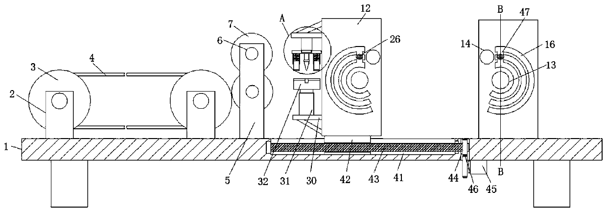
[0032] refer to Figure 1-6, a steel bar positioning and bending device for construction engineering, comprising a workbench 1, four corners of the lower end surface of the workbench 1 are welded with supporting legs, and a conveying mechanism is provided on one side of the upper end surface of the workbench 1, and the conveying mechanism is close to the workbench 1 One side of the center is provided with two supporting seats 5, and two supporting seats 5 are arranged and symmetrically fixed at the front and rear ends of the workbench 1. There are two, the outer wall of the rod of the positioning shaft 6 is fixedly connected with the positioning conveying roller 7 by screws, and the outer wall of the middle part of the positioning conveying roller 7 is provided with a limit groove 8, and the upper end surface of the workbench 1 is provided with bending plates 12 on both sides. , and the bending plate 12 is provided with two pieces and is arranged in an "L" shape, and the middl...

Embodiment 2

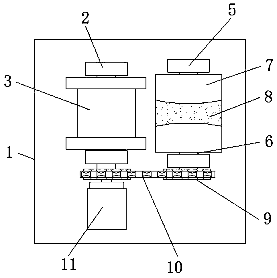
[0035] Such as Figure 1-2 As shown, this embodiment is basically the same as Embodiment 1. Preferably, the conveying mechanism includes a support base 2, and the support base 2 is provided with four and fixed on the upper end surface of the workbench 1 in a rectangular shape, two on the same side The upper end of support seat one 2 is all rotatably connected with belt pulley 3, is fixedly connected with conveyor belt 4 between two pulleys 3, and the front side of front end support seat one 2 and support seat two 5 is all fixedly connected with sprocket wheel 9, two Be connected with conveying chain 10 between sprocket wheel 9, and the rear side of rear end support base-2 is provided with servomotor-11, and the output end of servomotor-11 is fixedly connected with sprocket wheel 9 directly ahead.

[0036] In this embodiment, the rotation of the conveyor chain 10 is driven by the servo motor 11 to realize the rotation of the conveyor belt 4 and the positioning conveyor roller 7...

Embodiment 3

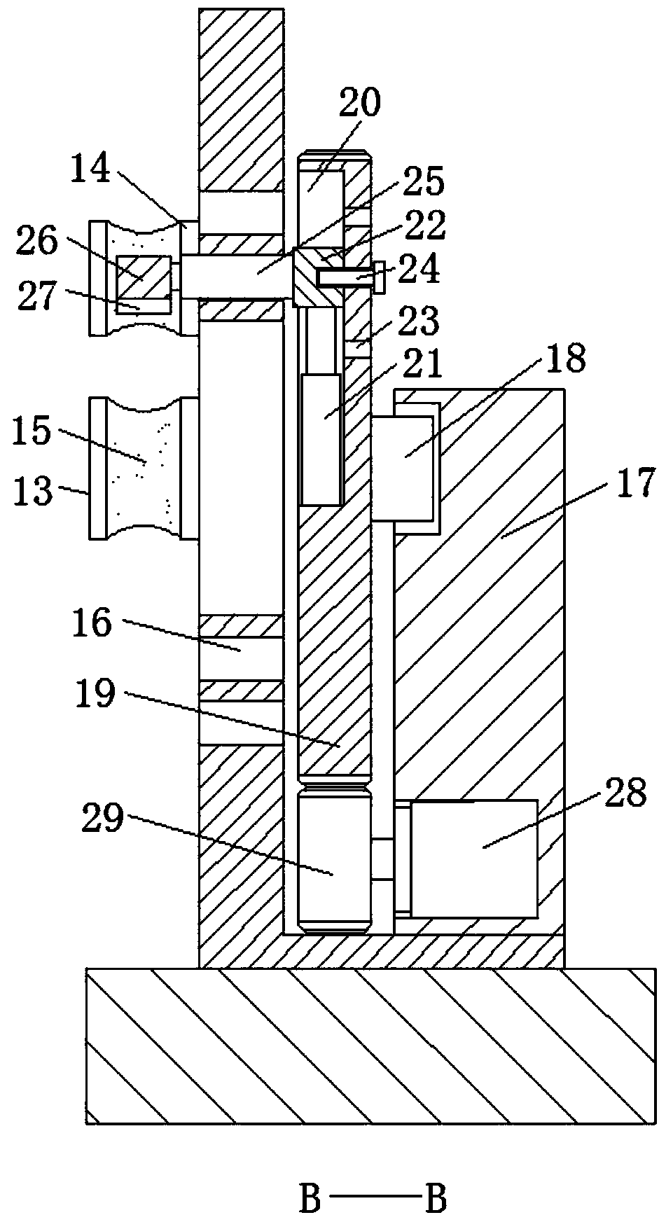
[0038] Such as figure 1 with 3 As shown, this embodiment is basically the same as Embodiment 1. Preferably, the bending groove 16 is a semicircular arc-shaped structure, and three bending grooves 16 are provided and distributed equidistantly on the bending plate 12. The three bending grooves 16 The upper part is also provided with a switching slot 47, and the switching slot 47 communicates with the three bending slots 16.

[0039] In this embodiment, three semi-arc-shaped bending grooves 16 are provided, and a switching groove 47 is provided on the upper part of the three bending grooves 16. The switching groove 47 communicates with the three bending grooves 16. Adjusting the position of the mounting block 22 facilitates the processing of steel bar elbows of different specifications, which brings convenience to production.


PUM


Abstract

The invention discloses a steel bar positioning and bending device for building engineering. The steel bar positioning and bending device for building engineering comprises a workbench, wherein support legs are welded to four corners of the lower end face of the workbench; a conveying mechanism is arranged on one side of the upper end face of the workbench; two second support seats are arranged onone side, close to the center of the workbench, of the conveying mechanism; the two support seats are symmetrically fixed to the front end and the rear end of the workbench; the upper ends of the twosupport seats are rotationally connected with two positioning shafts through rolling bearings; the outer wall of a rod body of each positioning shaft is fixedly connected with a positioning conveyingroller through screws; limiting grooves are formed in the outer wall of the middle of each positioning conveying roller; two bending plates are arranged on two sides of the upper end face of the workbench; and a bending column is welded to the middle of the front end face of each bending plate. By means of the steel bar positioning and bending device for building engineering, a steel bar after being subjected to fixed-length cutting can be bent at two ends at the same time, so that the working efficiency is greatly improved, and the production quality is guaranteed.

Description

technical field [0001] The invention relates to the technical field of construction engineering processing equipment, in particular to a positioning and bending device for steel bars used in construction engineering. Background technique [0002] With the rapid development of industry and construction, we are processing more and more steel bars. On construction sites, steel bars are generally used as the skeleton of concrete to improve the strength of concrete. Traditionally, the steel bars that play the role of skeleton are called Stirrups, a cylindrical steel bar is folded into polygonal, circular and other shapes to form stirrups. [0003] After searching, the patent application publication number 201811311661.0 discloses a steel bar bending device for construction engineering, including an abutment. The corners are fixed with universal wheels by bolts, and there are brake keys on the universal wheels. There is an inclined material guide opening on one side of the outer ...

Claims


Application Information

Patent Timeline
Patent Type & Authority Patents(China)
IPC IPC(8): B21F1/00B21F11/00B21F23/00
CPCB21F1/006B21F11/00B21F23/00
Inventor 赵勇刚窦晓磊管明明程朕李向军
Owner 安徽省天之泽工程科技有限公司
Why Eureka
Try Eureka