

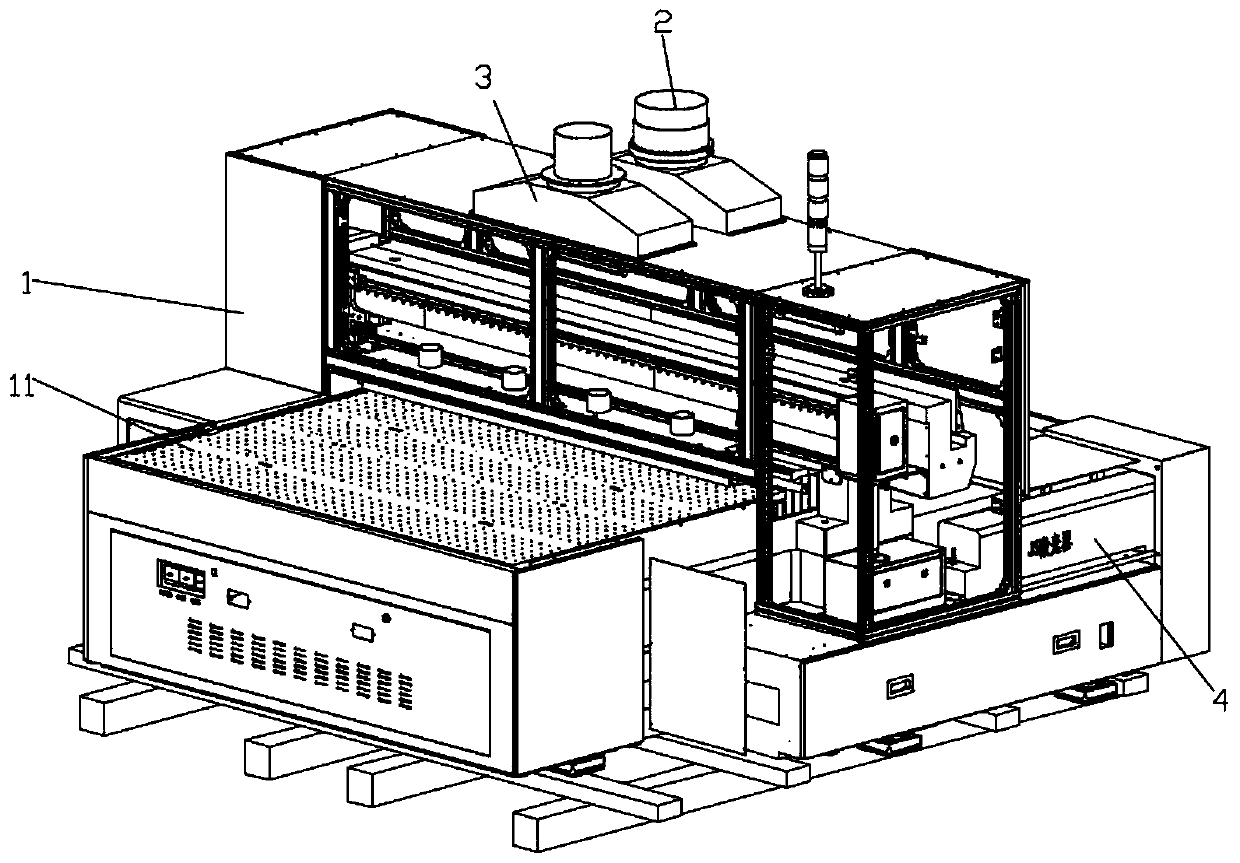
Laser machining equipment for light guide plate
A technology of laser processing and light guide plate, which is applied in laser welding equipment, metal processing equipment, welding equipment, etc., can solve the problems of laser refraction and influence on laser processing accuracy, and achieve the effect of ensuring accuracy, preventing electrostatic adsorption of dust, and good effect
- Summary
- Abstract
- Description
- Claims
- Application Information
AI Technical Summary
Problems solved by technology
Method used
Image

Examples
Embodiment
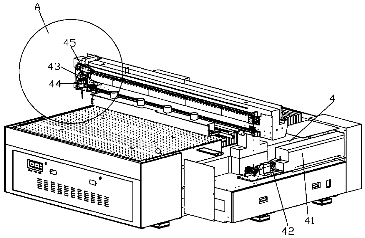
[0048] First place the light guide plate at the cutting station 11, then the laser generator 41 generates a laser beam, after the beam expander 42 enlarges the laser beam spot and optimizes the quality of the laser beam, then passes through the beam splitter Mirror 43, so that the laser beam is divided into multiple laser beams, and then irradiated onto the light guide plate through the focusing of the focusing mirror 44, and then the driving device can drive the moving plate 45 to move, so that the beam splitting mirror 43 Move with the focusing mirror 44 to complete the cutting of the light guide plate.
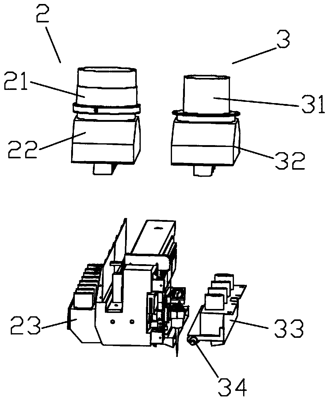
[0049] And in the whole cutting process, the blowing device blows synchronously, and the flowing gas enters the air inlet 31, then passes through the drying box 32 for drying, and finally blows out from the blowing part 33, so that the guide The dust and impurities on the light board are blown, so that the dust and impurities pass through the dust suction member 23 under th...
PUM
| Property | Measurement | Unit |
|---|---|---|
| Laser wavelength | aaaaa | aaaaa |
Abstract
Description
Claims
Application Information