
Automatic reinforcement mesh welding system

A technology of steel mesh and welding system, applied in the field of steel welding, can solve the problems of high labor intensity, high demand for manpower and high requirements for supporting facilities, and achieve the effects of reducing labor intensity of workers, improving dimensional accuracy, and simple and reliable equipment

Pending Publication Date: 2019-12-13
BEIJING YANTONG BUILDING COMPONENTS PROD +1
View PDF0 Cites 15 Cited by
  • Summary
  • Abstract
  • Description
  • Claims
  • Application Information

AI Technical Summary

Problems solved by technology

[0002] At present, the production methods of steel mesh are divided into two types: full manual binding and full-process automatic welding equipment. The disadvantages of full manual binding are: full manual work, manual lifting of steel bars and pre-arranging into finished product intervals, more manpower requirements, and space occupation Large, low efficiency; operators squatting work, labor-intensive; although the whole process of automatic welding equipment solves the problem of manual labor intensity, but the whole process of automatic welding equipment is mostly purchased imported equipment, the cost of imported equipment is extremely high, It takes up a lot of space, has high requirements for related supporting facilities, domestic equipment technology is immature, and has a high failure rate. Often, the entire welding equipment is shut down for maintenance due to a small link failure, which greatly affects the efficiency of the equipment.

Method used


Image

  • Automatic reinforcement mesh welding system
  • Automatic reinforcement mesh welding system
  • Automatic reinforcement mesh welding system

Examples


Embodiment Construction

[0028] The following will clearly and completely describe the technical solutions in the embodiments of the present invention with reference to the accompanying drawings in the embodiments of the present invention. Obviously, the described embodiments are only some, not all, embodiments of the present invention. Based on the embodiments of the present invention, all other embodiments obtained by persons of ordinary skill in the art without making creative efforts belong to the protection scope of the present invention.

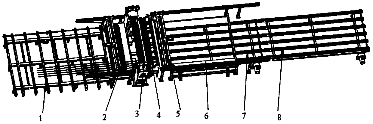
[0029] The object of the present invention is to provide an automatic reinforcement mesh welding system to solve the above-mentioned problems in the prior art. The system uses straightened and cut steel bars as raw materials, and has the characteristics of simple structure, energy saving and high efficiency.

[0030] In order to make the above objects, features and advantages of the present invention more comprehensible, the present invention will be further de...


PUM


Abstract

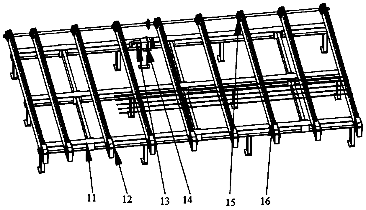
The invention discloses an automatic reinforcement mesh welding system. The automatic reinforcement mesh welding system comprises a vertical reinforcement distribution chain module, a vertical reinforcement forward stepper conveying module, a welding module, a transverse reinforcement supply module, a mesh stepper moving module and a mesh storage module arranged in sequence; a chain of the vertical reinforcement distribution chain module is used for placing vertical reinforcements; the vertical reinforcement forward stepper conveying module forwards conveys the distributed vertical reinforcements; the transverse reinforcement supply module with transverse reinforcements is positioned at the top of the welding module; the welding module is used for welding the vertical reinforcements and the transverse reinforcements; the mesh stepper moving module forwards shifts the welded reinforcements; and the mesh storage module is used for storing welded finished reinforcement meshes. The systemuses straightened cut reinforcements as raw materials, and has the characteristics of simple structure, energy conservation and high efficiency.

Description

technical field [0001] The invention relates to the technical field of steel bar welding, in particular to an automatic steel bar mesh welding system. Background technique [0002] At present, the production methods of steel mesh are divided into two types: full manual binding and full-process automatic welding equipment. The disadvantages of full manual binding are: full manual work, manual lifting of steel bars and pre-arranging into finished product intervals, more manpower requirements, and space occupation Large, low efficiency; operators squatting work, labor-intensive; although the whole process of automatic welding equipment solves the problem of manual labor intensity, but the whole process of automatic welding equipment is mostly purchased imported equipment, the cost of imported equipment is extremely high, It takes up a lot of space, has high requirements for related supporting facilities, domestic equipment technology is immature, and has a high failure rate. Of...

Claims


Application Information

Patent Timeline
IPC IPC(8): B23K31/02B23K37/00
CPCB23K31/02B23K37/00
Inventor 任成传张海龙杨思忠赵志刚陈宝宏刘晓中王文欢国仕蕾常龙王志礼
Owner BEIJING YANTONG BUILDING COMPONENTS PROD
Learn More