Device and method for measuring numerical control turning machining dynamic cutting force
What is Al technical title?
Al technical title is built by PatSnap Al team. It summarizes the technical point description of the patent document.
A measuring device and cutting force technology, applied in metal processing equipment, measuring/indicating equipment, metal processing machinery parts, etc., can solve the problems of complex installation, low measurement accuracy, measurement data error, etc., to reduce the interference of measurement data, Increased accuracy and reliability, results in precise data measurement
Pending Publication Date: 2019-12-13
HEBEI UNIV OF TECH
View PDF3 Cites 7 Cited by
Summary
Abstract
Description
Claims
Application Information
AI Technical Summary
This helps you quickly interpret patents by identifying the three key elements:
Problems solved by technology
Method used
Benefits of technology
Problems solved by technology
The installation and debugging technology of the device is relatively complicated, and it is easily affected by other factors of the machine tool
[0010] The document with the application number 201811211237.9 discloses an integrated turning force measurement tool system embedded with a film sensor. Although it can solve the problem of low measurement accuracy of the turning force measurement technology, it is easy to Errors in measurement data due to external force
[0011] In summary, the existing cutting force measurement devices for turning machining have the following problems: for different types and structural forms of CNC lathe cutting force measurement devices, a variety of connection mechanisms need to be added, the installation is complicated, debugging is difficult, and the versatility is poor; and during the measurement process , requires corresponding charge amplifiers and acquisition devices to obtain signals, and the peripheral wires directly affect the on-line measurement of dynamic cutting force. The measurement accuracy is low and the cost is high. Therefore, it is necessary to develop a dynamic cutting force measurement device for CNC turning embedded in the tool holder. To meet the online real-time measurement requirements for turning processing under actual cutting conditions
Method used
Image
Click on the blue label to locate the original text in one second.
Reading with bidirectional positioning of images and text.
Examples
Embodiment Construction
[0038] Specific examples of the present invention are given below. The specific embodiments are only used to further describe the present invention in detail, and do not limit the protection scope of the claims of the present application.
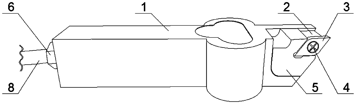
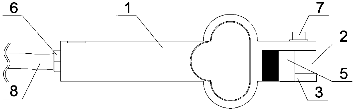
[0039] The invention provides a dynamic cutting force measuring device (referred to as the device, see Figure 1-6), including knife bar 1, fixed knife seat 2, blade 3 and anti-skid pad 5; described anti-skid pad 5 is fixed on the right front end of knife bar 1 outside by fixing bolt 7, is used for assisting fixed blade 3; fixed knife seat 2 It is fixed on the outside of the knife bar 1 and is located at the top right side of the anti-skid pad 5; the blade 3 is threadedly connected to the fixed knife seat 2 through the mounting bolt 4 and is located at the top right side of the anti-slip pad 5;
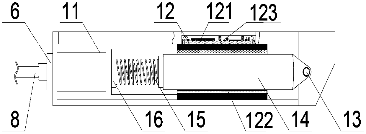
[0040] It is characterized in that the device also includes a data processing module 11, a force sensor 12, a linkage pin hole 13, an exciting ro...
PUM
Abstract
The invention discloses a device and a method for measuring numerical control turning machining dynamic cutting force. The device comprises a cutter bar, a fixed cutter seat, a blade, an anti-skid pad, a data processing module, a force sensor, a shock excitation rod, a limiting spring, a spring base and a data bus, wherein the data processing module, the force sensor, the shock excitation rod, thelimiting spring and the spring base are arranged inside the cutter bar, the force sensor comprises a force sensitive element, a conversion element and a PCB circuit board, and a filter, an amplifierand a power supply module are integrated on the PCB circuit board. The shock excitation rod and the blade arranged inside the cutter bar are connected together through a linkage pin hole and a linkagebolt, in the cutting process, force borne by the blade is transmitted to the shock excitation rod in real time, the shock excitation rod can acquire the real stress condition of the blade in the cutting process in real time, the force sensor is embedded in the interior of the cutter bar in an integrated mode and is positioned around the shock excitation rod, so that the influence of external force on the force sensor can be effectively avoided, and meanwhile, data measuring is accurately carried out on the shock excitation rod.
Description
technical field [0001] The invention belongs to the field of dynamic cutting force testing, in particular to a device and method for measuring dynamic cutting force in numerically controlled turning. Background technique [0002] Cutting force is an important basis for rational design and use of machine tools, cutting tools and fixtures. The dynamic cutting force in the process of CNC turning directly affects tool wear, durability, cutting heat, surface quality of machined parts and cutting vibration, and even affects the cutting stability of the CNC turning process system. In the actual machining process, in order to optimize the machining process parameters, monitor tool wear and tear and machine tool vibration online, it is necessary to measure the dynamic cutting force in real time. The empirical calculation formula of cutting force is: [0003] [0004] In formula 1), F c Main cutting force; C Fc is the coefficient; a P is the back cutting amount; f is the feed ...
Claims
Application Information
Patent Timeline
Application Date:The date an application was filed.
Publication Date:The date a patent or application was officially published.
First Publication Date:The earliest publication date of a patent with the same application number.
Issue Date:Publication date of the patent grant document.
PCT Entry Date:The Entry date of PCT National Phase.
Estimated Expiry Date:The statutory expiry date of a patent right according to the Patent Law, and it is the longest term of protection that the patent right can achieve without the termination of the patent right due to other reasons(Term extension factor has been taken into account ).
Invalid Date:Actual expiry date is based on effective date or publication date of legal transaction data of invalid patent.