
Crystal rod outer diameter grinding equipment for semiconductor devices

A technology of components and semiconductors, which is applied in the field of grinding equipment for the outer diameter of crystal ingots used in semiconductor components, can solve problems that affect the grinding accuracy, uniform grinding, and the surface of difficult crystal ingots, so as to improve the grinding accuracy, improve the centering accuracy, reduce the The effect of the action steps

Active Publication Date: 2019-12-13
奥准企业发展上海有限公司
View PDF8 Cites 2 Cited by
  • Summary
  • Abstract
  • Description
  • Claims
  • Application Information

AI Technical Summary

Problems solved by technology

[0003] (1) Before grinding the crystal ingot, it is necessary to use a special fixture to clamp the two ends of the crystal ingot, and then use rolling to grind the outer wall of the crystal ingot. Since most of the fixtures currently used are mostly manual clamping, the clamping It is difficult to ensure the alignment accuracy between the clamp and the ingot when it is tight. Once the clamping position deviates greatly, it will make it difficult for the roller mill to grind the surface of the ingot evenly, so that the shape of the ingot after grinding cannot meet the work needs;
[0004] (2) When using a jig to clamp the crystal ingot, since the two ends of the ingot are blocked by the jig, the roller mill cannot fully grind the ingot at one time, and it is necessary to wait for the middle of the ingot to be ground before another crystal ingot Grinding at both ends will easily cause the accumulation of errors during the movement of the ingot, which will further affect the grinding accuracy

Method used


Image

  • Crystal rod outer diameter grinding equipment for semiconductor devices
  • Crystal rod outer diameter grinding equipment for semiconductor devices
  • Crystal rod outer diameter grinding equipment for semiconductor devices

Examples


Embodiment Construction

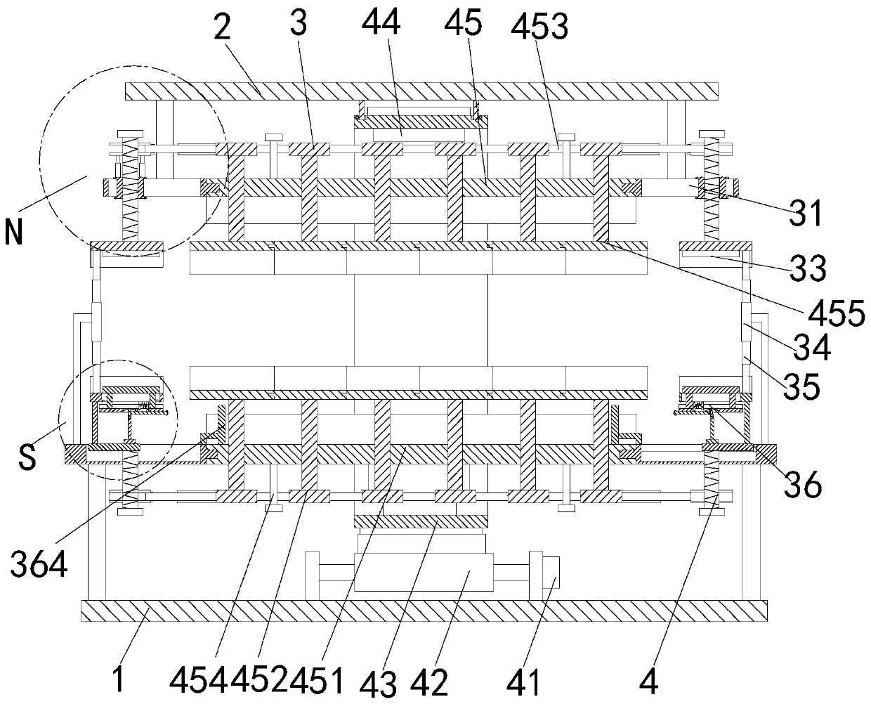
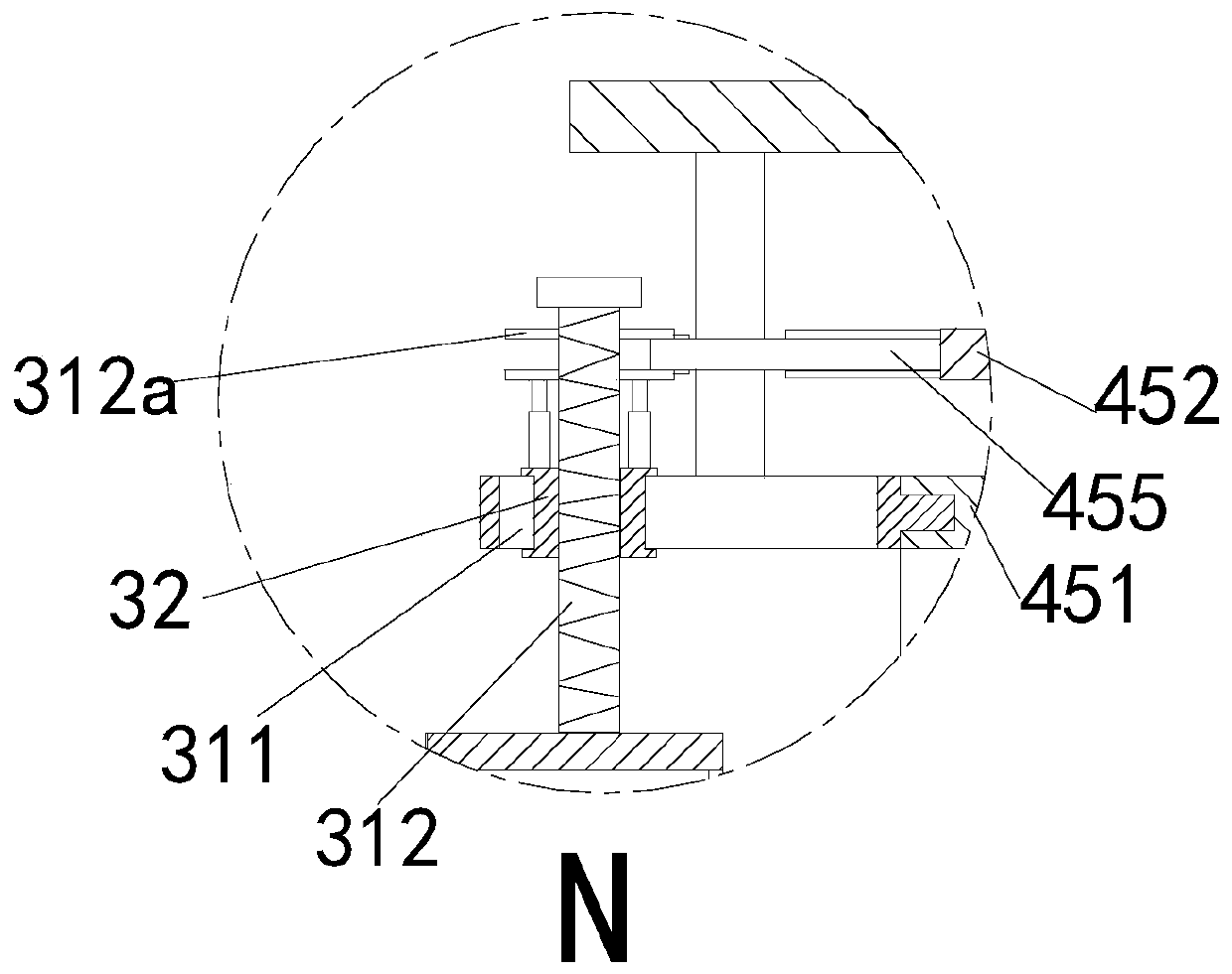
[0027] In order to make the technical means realized by the present invention, creative features, goals and effects easy to understand, the following combination Figure 1 to Figure 4 , to further elaborate the present invention.

[0028] A crystal bar outer diameter grinding device for semiconductor components, comprising a workbench 1, a mounting frame 2, a support mechanism 3 and a grinding mechanism 4, the support mechanism 3 is installed on the upper end of the workbench 1, and the upper end of the support mechanism 3 is arranged There is a mounting frame 2, and a grinding mechanism 4 is installed at the lower end of the mounting frame 2; wherein:

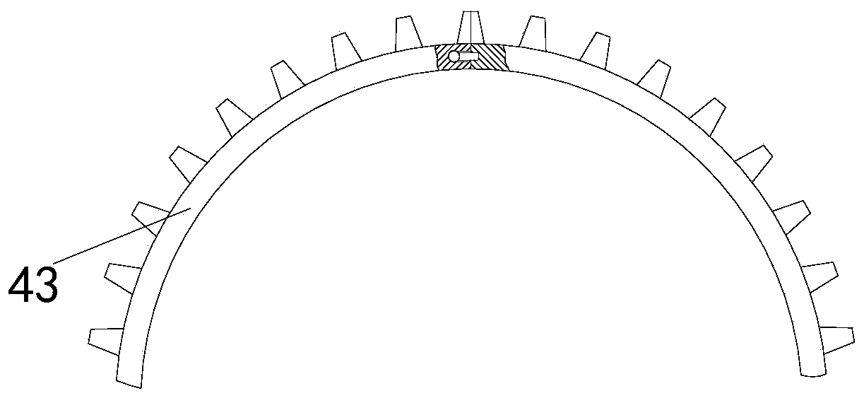
[0029] The grinding mechanism 4 includes a driving motor 41, a driving gear 42, a driven gear 43, a connecting plate 44 and a grinding branch chain 45. The driving motor 41 is installed on the workbench 1 through a motor base, and the output shaft of the driving motor 41 passes through a shaft coupling. It is connected with o...


PUM


Abstract

The invention relates to crystal rod outer diameter grinding equipment for semiconductor devices. The equipment comprises a worktable, a mounting frame, a support mechanism and a grinding mechanism; the support mechanism is mounted at the upper end of the worktable; the mounting frame is arranged at the upper end of the support mechanism; the grinding mechanism is mounted at the lower end of the mounting frame, and comprises a driving motor, a driving gear, a driven gear, a connecting plate and a grinding support chain; the support mechanism comprises a butt joint branch chain, a slide block,a pressing plate, a fixed plate, an extension plate, a support branch chain and an electric slide block; and the grinding support chain comprises a working plate, an adjusting rod, a transverse plate,an adjusting bolt and a grinding plate. Through cooperation of the support mechanism and the grinding mechanism during working, the equipment achieves the purpose of alternately clamping the left andright ends of crystal rods, so that the overall grinding work of the crystal rods is once finished, the operation steps are reduced, the grinding precision is improved, the clamping of the crystal rods by a manual mode is not needed, and the centering precision is improved.

Description

technical field [0001] The invention relates to the field of crystal rod processing, in particular to a crystal rod outer diameter grinding device for semiconductor components. Background technique [0002] Wafer is the basic raw material required for semiconductor components. Wafer production includes two steps: ingot manufacturing and wafer manufacturing. Ingot is the raw material for making chips. During the growth process of the ingot, the outer diameter and roundness have certain deviations, and the outer cylindrical surface is also uneven, so the outer diameter must be trimmed and ground to make the size and shape errors less than the allowable deviation. In the actual grinding process, there are the following problems: [0003] (1) Before grinding the crystal ingot, it is necessary to use a special fixture to clamp the two ends of the crystal ingot, and then use rolling to grind the outer wall of the crystal ingot. Since most of the fixtures currently used are mostly...

Claims


Application Information

Patent Timeline
Patent Type & Authority Applications(China)
IPC IPC(8): B24B37/02B24B37/27B24B37/34
CPCB24B37/02B24B37/27B24B37/34
Inventor 吴信任沈方园
Owner 奥准企业发展上海有限公司
Learn More