Eureka AIR delivers breakthrough ideas for toughest innovation challenges, trusted by R&D personnel around the world.

Double-layer comprehensive pipe gallery of common personnel passageway

A technology of integrated pipe gallery, entrance and exit, applied in artificial islands, water conservancy projects, underwater structures, etc., can solve problems such as the increase of above-ground structures, the cross-section space of large roads, and the uneven width of roads, so as to reduce the impact on the environment and city appearance. The effect of reducing the number of nodes and improving the overall image

Pending Publication Date: 2019-12-13
CISDI ENG CO LTD
View PDF0 Cites 0 Cited by
  • Summary
  • Abstract
  • Description
  • Claims
  • Application Information

AI Technical Summary

Problems solved by technology

[0003] At present, the common comprehensive utility gallery is a single-layer structure. In order to accommodate various pipelines and other facilities, it needs to occupy a large cross-sectional space of the road. However, the width of the roads varies, and the available cross-sectional space of some roads is limited, which cannot meet the construction requirements. demand, leading to restrictions on the construction of comprehensive utility corridors
In addition, each compartment of the traditional comprehensive utility gallery is equipped with personnel entrances and exits connected to the road surface. There are many personnel entrances and exits nodes, and the corresponding above-ground structures increase, which increases the amount of engineering and construction costs, and affects the urban landscape.

Method used


Image

  • Double-layer comprehensive pipe gallery of common personnel passageway
  • Double-layer comprehensive pipe gallery of common personnel passageway
  • Double-layer comprehensive pipe gallery of common personnel passageway

Examples


Embodiment Construction

[0024] The preferred embodiments of the present invention will be described in detail below with reference to the accompanying drawings.

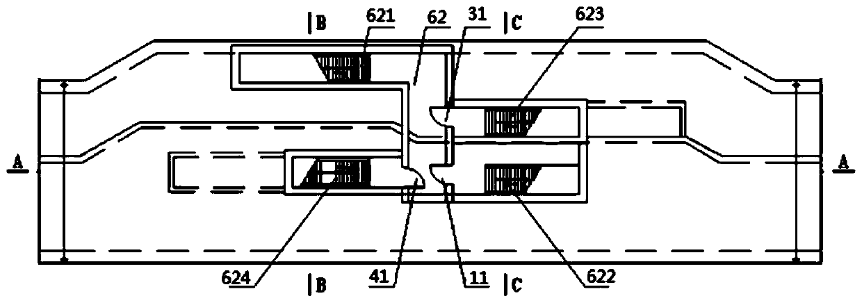
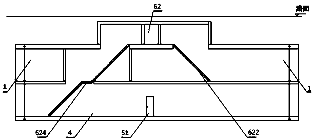
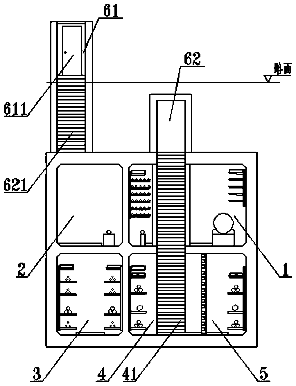
[0025] Such as Figure 1 ~ Figure 4 As shown, this embodiment provides a double-layer comprehensive pipe gallery with shared personnel entrances and exits, including a comprehensive cabin 1, a gas cabin 2, a high-voltage electric cabin 3, and an ultra-high-voltage electric cabin. The comprehensive cabin 1 and the gas cabin 2 are isolated from each other. In the upper layer, the high-voltage power cabin 3 and the ultra-high-voltage power cabin are arranged in isolation from each other in the lower layer to form a double-layer structure; along the length direction of the double-layer integrated pipe gallery, there are personnel entrance and exit node structures 6 arranged at intervals, and the personnel entrance and exit node structures 6 It includes the personnel entrance and exit node above-ground structure 61 arranged above the ground, and...


PUM


Abstract

The invention relates to a double-layer comprehensive pipe gallery of a common personnel passageway, and belongs to the technical field of comprehensive pipe galleries. The double-layer comprehensivepipe gallery of the common personnel passageway comprises a comprehensive cabin, a gas cabin, a high-voltage power cabin and an ultrahigh-voltage power cabin, wherein the comprehensive cabin and the gas cabin are arranged on an upper layer in an isolated mode, and the high-voltage power cabin and the ultrahigh-voltage power cabin are arranged on a lower layer in an isolated mode, so that a double-layer structure is formed. Personnel passageway node structures are arranged in the length direction of the double-layer comprehensive pipe galley at intervals and include over-ground personnel passageway node structures arranged on the ground and personnel passageway node interlayer structures which are arranged under the ground and above the comprehensive cabin and the gas cabin, upwards communicate with the over-ground personnel passageway node structures, and downward communicate with the comprehensive cabin, the high-voltage power cabin and the ultrahigh-voltage power cabin separately. According to the double-layer comprehensive pipe gallery, the space occupied by the road cross section is reduced, all the cabins share the personnel passageway, workers can carry out maintenance work conveniently by carrying tools, the number of personnel passageway nodes is reduced, the construction cost is reduced, and the urban attractiveness is improved.

Description

technical field [0001] The invention belongs to the technical field of comprehensive pipe gallery, and relates to a double-layer comprehensive pipe gallery with shared personnel entrances and exits. Background technique [0002] The comprehensive pipe gallery is a municipal infrastructure that integrates various engineering pipelines such as electric power, communication, gas, heating, water supply and drainage. The construction of comprehensive pipe gallery is of great significance for effectively solving the planning and management of urban underground pipelines, avoiding repeated excavation of roads caused by traditional direct buried pipeline methods when pipeline expansion or maintenance is required, and promoting my country's new urbanization process. [0003] At present, the common comprehensive utility gallery is a single-layer structure. In order to accommodate various pipelines and other facilities, it needs to occupy a large cross-sectional space of the road. Howe...

Claims


Application Information

Patent Timeline
Patent Type & Authority Applications(China)
IPC IPC(8): E02D29/045
CPCE02D29/10
Inventor 徐裴森陈乐李劼冯远彬李榕
Owner CISDI ENG CO LTD
Why Eureka
Eureka Blog
Learn More