Underwater desilting robot

A technology of robots and high-pressure water, which is applied to earth movers/shovels, mechanically driven excavators/dredgers, construction, etc., can solve problems such as noise pollution, time-consuming and labor-consuming, and low dredging efficiency, and achieve Ease of absorption and increased mud concentration

Pending Publication Date: 2019-12-13
SAFECLEEN TECH
View PDF0 Cites 2 Cited by
  • Summary
  • Abstract
  • Description
  • Claims
  • Application Information

AI Technical Summary

Problems solved by technology

[0002] With the increasing emphasis on environmental protection in our country, the dredging methods for urban rivers and lakes have become increasingly backward and cannot meet the national construction method requirements for the environment.
For example, the old treatment methods generally include: the river is pumped with cofferdams, and then dredged, the disadvantage is time-consuming and labor-intensive, and the efficiency is extremely low
The lake is mainly constructed by cutter suction dredgers, but cutter suction dredgers are likely to cause noise pollution to the surrounding environment
In response to the above shortcomings, some units in my country have also developed some underwater dredging equipment, but the suction part still adopts the method of auger and liquid suction. For the silt with high concentration and strong adhesion, it is difficult to inhale directly through the suction part. It has the disadvantages of low slurry suction concentration and low dredging efficiency

Method used


Image

  • Underwater desilting robot
  • Underwater desilting robot
  • Underwater desilting robot

Examples


Embodiment Construction

[0021] The following will clearly and completely describe the technical solutions in the embodiments of the present invention in conjunction with the embodiments of the present invention. Obviously, the described embodiments are only part of the embodiments of the present invention, not all of them. Based on the implementation manners in the present invention, all other implementation manners obtained by persons of ordinary skill in the art without making creative efforts belong to the scope of protection of the present invention.

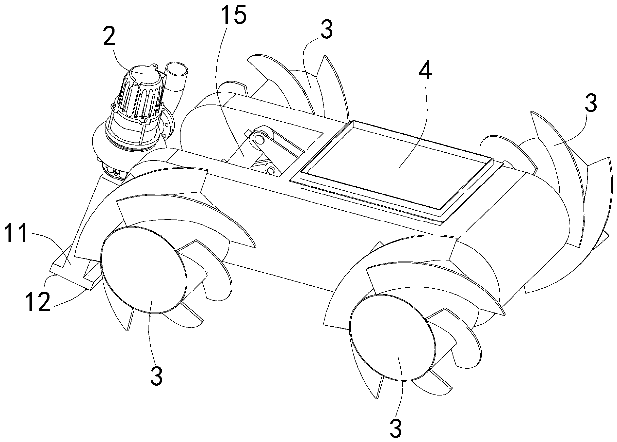
[0022] Such as figure 1 As shown, the underwater dredging robot of the present invention includes a high-pressure pump (not shown in the figure), a frame body 4, a drive wheel 3, a centrifugal sewage suction pump 2 and a jet suction cup mechanism 1.

[0023] The frame body 4 provides support and connects the driving wheel 3 and the jet suction cup mechanism 1 respectively, and the existing underwater working robot frame can be used.

[0024] The d...


PUM


Abstract

The invention provides an underwater desilting robot. By arranging nozzles around a silt suction cavity, high-speed jet flow is sprayed out to cut and disturb silt, the silt concentration is greatly increased, meanwhile parallel water curtains formed by the high-speed jet flow form a sectional negative pressure area, and the suction effect of a suction cup is ensured. By arranging a link mechanismin cooperation with a wheel-drive vehicle frame, underwater operations can be quite conveniently conducted, and the height of the suction cup is adjusted according to the silt height. By arranging adriving wheel comprising a roller and a spiral rib, on one hand, walking in the silt is facilitated, and wheels are prevented from sinking in the silt; and on the other hand, the silt can be stirred and dispersed so as to be conveniently sucked.

Description

technical field [0001] The invention relates to the field of underwater dredging equipment, in particular to an underwater dredging robot. Background technique [0002] With the increasing emphasis on environmental protection in our country, the dredging methods for urban rivers and lakes have become increasingly backward, and cannot meet the national requirements for environmental construction methods. For example, the old treatment methods generally include: the river channel is pumped with a cofferdam, and then dredged, which is time-consuming and labor-intensive, and the efficiency is extremely low. The lake is mainly constructed by cutter suction dredgers, but cutter suction dredgers are likely to cause noise pollution to the surrounding environment. In response to the above shortcomings, some units in my country have also developed some underwater dredging equipment, but the suction part still adopts the method of auger and liquid suction. For the silt with high conce...

Claims


Application Information

Patent Timeline
Patent Type & Authority Applications(China)
IPC IPC(8): E02F3/88E02F3/90E02F3/92E02F5/28
CPCE02F3/88E02F3/8858E02F3/8866E02F3/90E02F3/92E02F3/9243E02F3/925E02F5/28E02F5/287
Inventor 赵明星傅磊崔健刘学进张俊峰汪宗胜黄蕾梅邵锋
Owner SAFECLEEN TECH
Why Eureka
Try Eureka