Cascaded utilization system and method for waste heat of oxygen production process

A waste heat and cascade technology, applied in the direction of refrigerators, refrigeration components, refrigeration and liquefaction, etc., can solve the problems of ineffective utilization, inability to make full use of waste heat resources, and failure to take air temperature into account, so as to improve waste heat utilization efficiency and reduce maintenance Cost and energy saving effect

Active Publication Date: 2019-12-13
ANGANG STEEL CO LTD
View PDF7 Cites 1 Cited by
  • Summary
  • Abstract
  • Description
  • Claims
  • Application Information

AI Technical Summary

Problems solved by technology

It is mainly reflected in the fact that the existing air compressor waste heat utilization system and method in the oxygen production process do not take into account the low temperature of the air after the first-stage compression of the air compressor in actual operation, and the waste heat cannot be effectively used after recovery; at the same time, how effective is the waste heat recovery of the air compressor? To adapt to fluctuations in thermal user demand, there is no solution
Moreover, the waste heat resources in the oxygen production process are mainly used for domestic heating after recovery, and domestic heating is usually limited by the heat supply and heating radius, and the large amount of waste heat resources in the oxygen production process cannot be fully utilized.

Method used


Image

  • Cascaded utilization system and method for waste heat of oxygen production process

Examples


Embodiment 1

[0036] Low temperature heat exchanger non-operational mode:

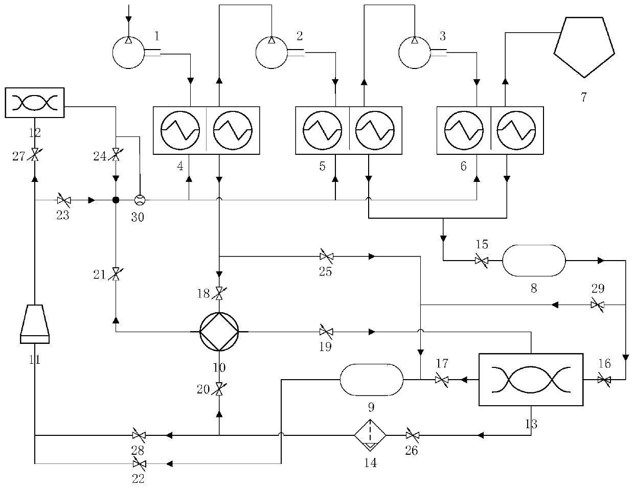
[0037] In the non-operation mode of the low-temperature heat exchanger, the on-off valves 15, 16, 22, 23, and 25 are in an open state, and the on-off valves 19, 21, 28, and 29 are in a closed state; Valves 18, 20, 26, 27 are closed. The design maximum water storage capacity of the high temperature water storage tank 13 is 1800m 3 .

[0038] 150,000Nm 3 / h The normal temperature and normal pressure air passes through the primary compression 1 of the air compressor and the temperature reaches 95 °C, and then enters the primary heat exchanger 4 for heat exchange with 35 °C cooling water. After the heat exchange, the compressed air temperature is 40 °C and enters the air compressor. Two-stage compression, air compressor three-stage compression, the temperature of the two-stage compressed air and the third-stage compressed air can reach 120 ℃, after compression, it enters the second-stage heat exchanger 5 and the thir...

Embodiment 2

[0044] Low temperature heat exchanger operating mode:

[0045] In the low temperature heat exchanger operating mode, the on-off valves 15, 16, 19, 21, 23, 28 are in the open state, the on-off valves 22, 25, 29 are in the closed state; the on-off valves 18, 20, 24, 26, 27 are in In the open state, the on-off regulating valve 17 is in the closed state. The design maximum water storage capacity of the high temperature water storage tank 13 is 1800m 3 .

[0046] 150,000Nm 3 / h The normal temperature and normal pressure air passes through the primary compression 1 of the air compressor and the temperature reaches 95 °C, and then enters the primary heat exchanger 4 for heat exchange with 35 °C cooling water. After the heat exchange, the compressed air temperature is 40 °C and enters the air compressor. Two-stage compression, air compressor three-stage compression, the temperature of the two-stage compressed air and the third-stage compressed air can reach 120 ℃, after compression...


PUM


Abstract

The invention relates to the technical field of energy conservation in the iron and steel industry, in particular to a cascaded utilization system and method for waste heat of an oxygen production process. The cascaded utilization system comprises a primary air compressor, a secondary air compressor, a tertiary air compressor, a primary heat exchanger, a secondary heat exchanger, a tertiary heat exchanger, an oxygen generator, a refrigerating user, a heating user, a heat pump unit, a cooling tower, a water supply pool, a high-temperature water storage tank, a low-temperature liquid heat exchanger, a flow meter and various valves, wherein the valves are connected among the above devices. The cascaded utilization method for the waste heat of the oxygen production process has two operating models: one is the low-temperature heat exchanger non-operating mode and the other is the low-temperature heat exchanger operating mode. Consequently, the cascaded utilization of the waste heat of the oxygen production process for production and lift heating in the oxygen process can be achieved, and waste heat of the air compressors can be utilized for effectively adapting to the demand fluctuations of the heating user.

Description

technical field [0001] The invention relates to the technical field of energy saving in the iron and steel industry, and in particular, to a system and method for the cascade utilization of waste heat in an oxygen production process. Background technique [0002] Iron and steel enterprises need a lot of high-purity oxygen, nitrogen and other energy media in the smelting and production process. Therefore, large iron and steel enterprises usually have their own oxygen production processes, with multiple oxygen generators and oxygen pipe networks. The oxygen produced by the oxygen generators passes through the pipes. The network is sent to each oxygen-consuming user; when a certain oxygen generator in the oxygen production process fails, and the amount of oxygen produced cannot meet the needs of downstream oxygen-consuming users, the pressure of the oxygen pipe network will be insufficient, and the oxygen generator will fail. The fault generally takes up to 15-20 hours to recov...

Claims


Application Information

Patent Timeline
Patent Type & Authority Applications(China)
IPC IPC(8): F25B27/02F25B41/04F25J5/00F25B41/20
CPCF25B27/02F25J5/002F25B2400/075F25B41/20Y02A30/274
Inventor 徐伟倪健勇马光宇张天赋王东山刘冬杰王永陈鹏胡绍伟王超
Owner ANGANG STEEL CO LTD
Why Eureka
Try Eureka