Cooling plate and manufacturing method thereof

A manufacturing method and heat dissipation plate technology, applied in heat exchange equipment, indirect heat exchangers, lighting and heating equipment, etc., can solve problems such as difficult installation, low heat transfer and heat transfer efficiency, and large thermal resistance

Pending Publication Date: 2019-12-13
ZHEJIANG JIAXI TECH CO LTD
View PDF0 Cites 7 Cited by
  • Summary
  • Abstract
  • Description
  • Claims
  • Application Information

AI Technical Summary

Problems solved by technology

[0003] In view of the above-mentioned shortcomings of the prior art, the purpose of the present invention is to provide a heat sink and its manufacturing method, which are used to

Method used


Image

  • Cooling plate and manufacturing method thereof
  • Cooling plate and manufacturing method thereof
  • Cooling plate and manufacturing method thereof

Examples


Embodiment Construction

[0023] The following describes the implementation of the present invention through specific examples. Those skilled in the art can easily understand other advantages and effects of the present invention from the content disclosed in this specification. The present invention can also be implemented or applied through other different specific implementations. , the details in this specification can also be modified or changed based on different viewpoints and applications without departing from the spirit of the present invention.

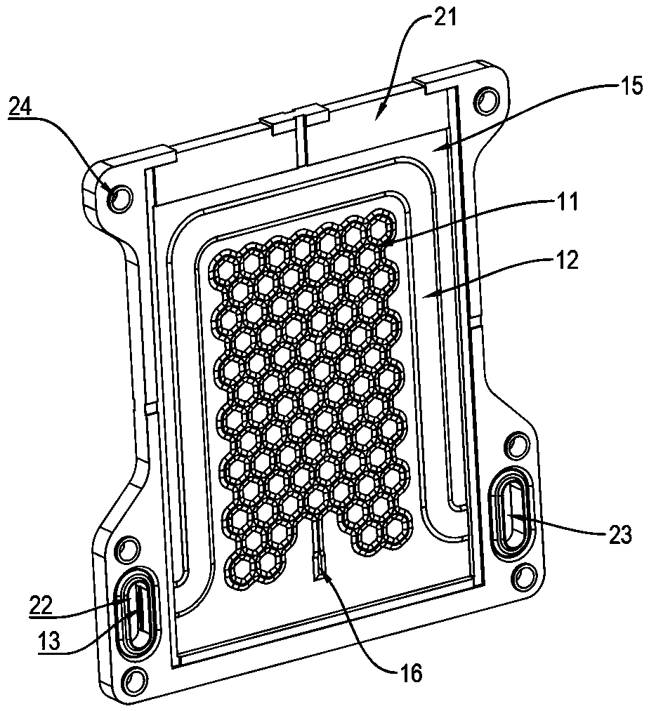
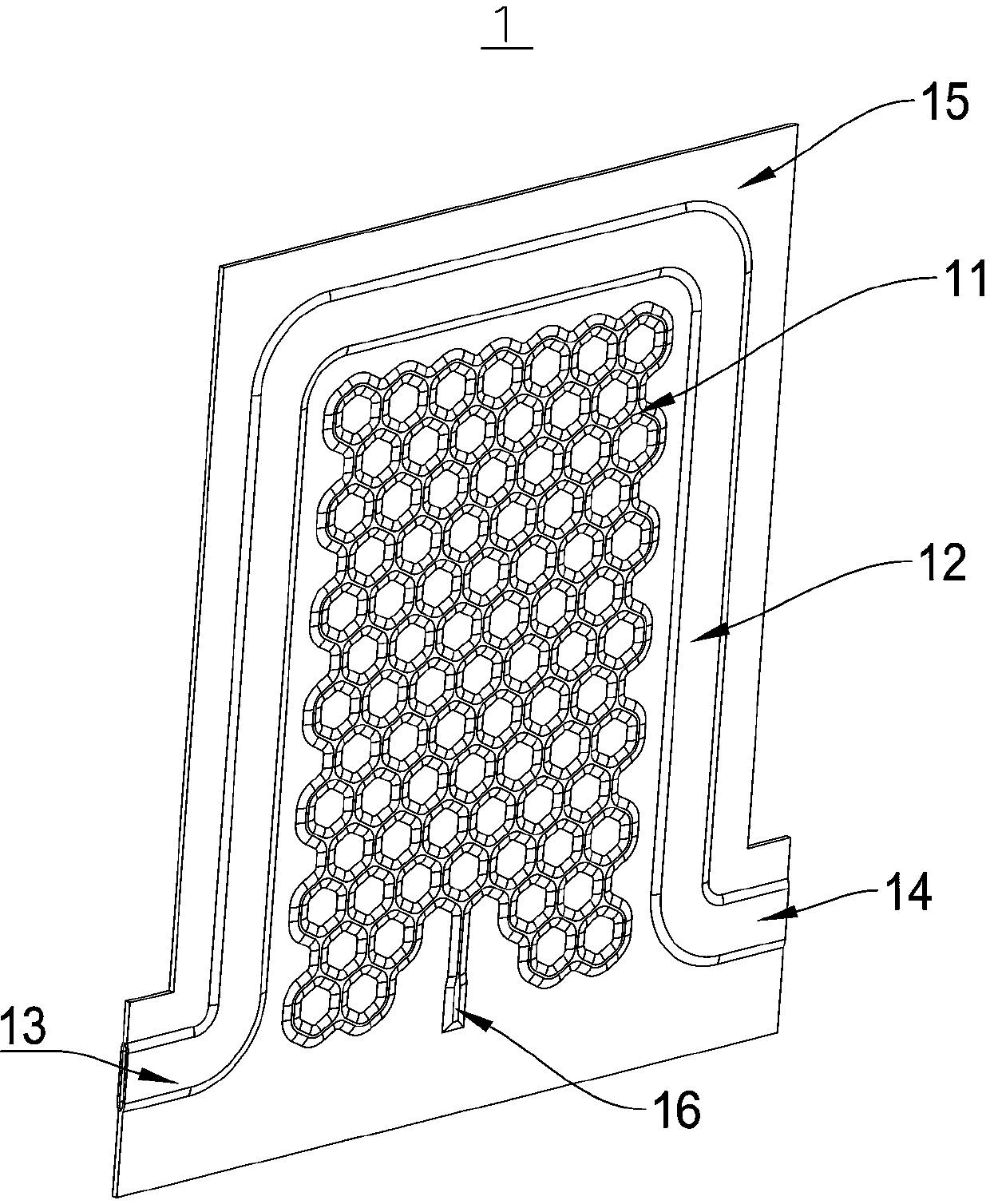
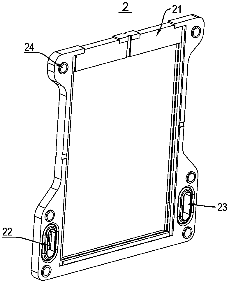
[0024] The embodiment of the present invention proposes a cooling plate, please refer to figure 1 As shown, the heat dissipation plate includes a metal plate 1 and a frame 2 .

[0025] The metal plate 1 includes a thermal superconducting circuit 11 and a refrigerant channel 12 , and the thermal superconducting circuit 11 is filled with a heat transfer fluid (not shown). It can be understood that, the thermal superconducting circuit 11 on the metal p...


PUM


Abstract

The invention provides a cooling plate and a manufacturing method of the cooling plate. The cooling plate comprises a metal plate and a frame. Closed thermal superconduction pipelines are arranged inthe metal plate and communicate with one another. Each thermal superconduction pipeline is filled with a heat transfer working medium. The metal plate further comprises a refrigerant channel, so thatthe cooling effect of the cooling plate can be improved. The metal plate and the frame are tightly connected through an insert injection molding technology. The frame is divided by the metal plate into at least one containing cavity.

Description

technical field [0001] The invention relates to the field of heat dissipation plates, in particular to a heat dissipation plate and a manufacturing method thereof. Background technique [0002] At present, the materials used for heat exchange in the industry mainly use heat sinks. At present, most heat sinks use single-pipelines, multiple bending fluid passages in order to maximize the heat dissipation area, or use additional cooling fins. Due to the limitation of the thermal conductivity of the material and the volume of the board, these two methods have a large thermal resistance, and the fluid pipeline / radiating fin cannot cover the entire board surface, resulting in uneven temperature on the board surface and unable to exert its heat dissipation effect , At the same time, because the pipeline system is too long, the fluid flow resistance in the pipeline in the heat exchange plate is very large, resulting in a decrease in the energy efficiency of the system. In addition,...

Claims


Application Information

Patent Timeline
IPC IPC(8): F28D15/00F28F3/02B23P15/26
CPCF28D15/00F28F3/02B23P15/26
Inventor 郭良银周颖郭鹏张毅鸿贺晗张晖
Owner ZHEJIANG JIAXI TECH CO LTD
Why Eureka
Try Eureka