High-speed high-power permanent magnet synchronous motor rotor

A permanent magnet synchronous motor, high-power technology, applied to synchronous motors with stationary armatures and rotating magnets, magnetic circuit rotating parts, magnetic circuits, etc., can solve the problem that the prestress cannot be adjusted according to needs, and the rotor sheath Difficulties in suiting

Active Publication Date: 2019-12-13
HARBIN INST OF TECH
View PDF5 Cites 1 Cited by
  • Summary
  • Abstract
  • Description
  • Claims
  • Application Information

AI Technical Summary

Problems solved by technology

[0005] The purpose of the present invention is to solve the problems that existing high-speed and high-power permanent magnet synchronous motors are difficult to fit the rotor sheath and the prestress cannot be adjusted acc

Method used


Image

  • High-speed high-power permanent magnet synchronous motor rotor
  • High-speed high-power permanent magnet synchronous motor rotor
  • High-speed high-power permanent magnet synchronous motor rotor

Examples


Embodiment 1

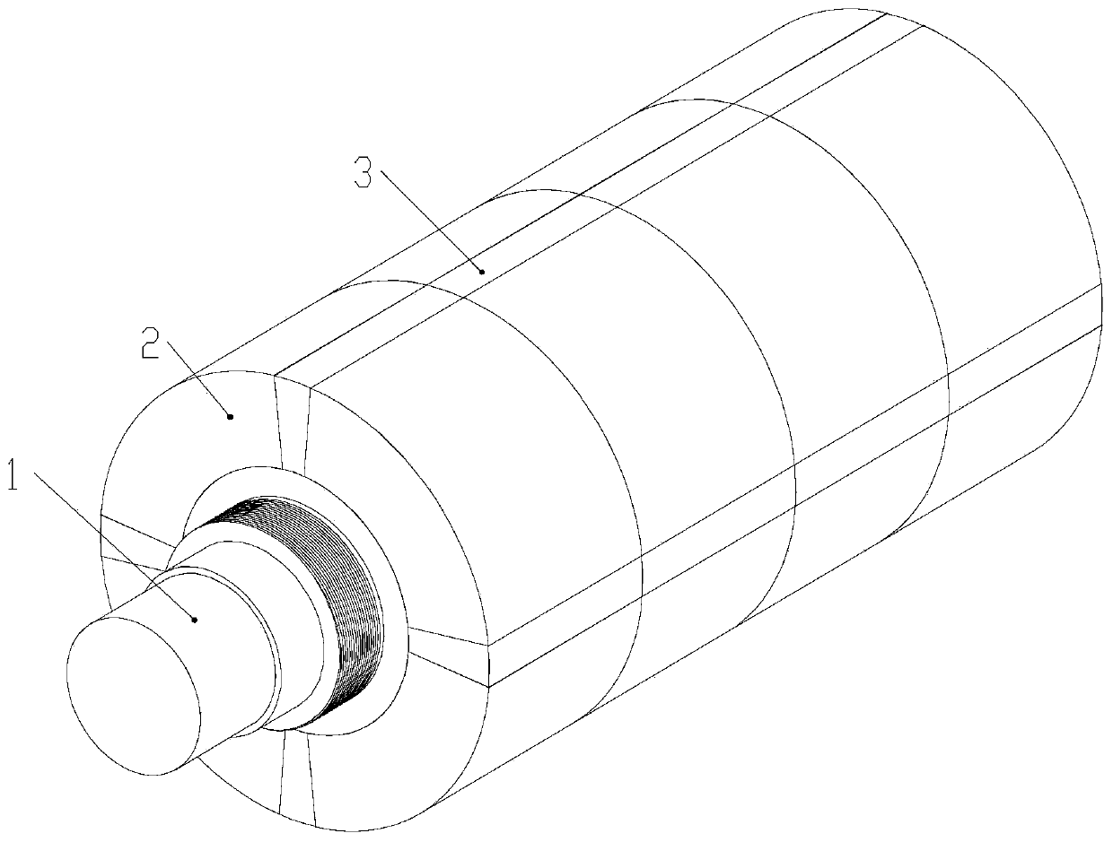
[0133] see figure 1 Describe the present embodiment 1, the high-speed and high-power permanent magnet synchronous motor rotor described in the present embodiment 1 includes a rotating shaft 1, a conical main permanent magnet 2, a conical auxiliary permanent magnet 3, a preload nut and a sheath;

[0134] The rotating shaft 1 is a cylindrical body tapered at both ends, and the two ends of the rotating shaft 1 are provided with external threads;

[0135] The taper of the inner surface of the tapered main permanent magnet 2 and the tapered auxiliary permanent magnet 3 is the same as the taper of the shaft body of the rotating shaft 1;

[0136] All the conical main permanent magnets 2 and all the conical auxiliary permanent magnets 3 are arranged on the outer surface of the rotating shaft 1, and form a cylindrical structure enclosing the shaft body of the rotating shaft 1, and along the circumferential direction, a total of 2P columns of main permanent magnets are formed Queues, e...

Embodiment 2

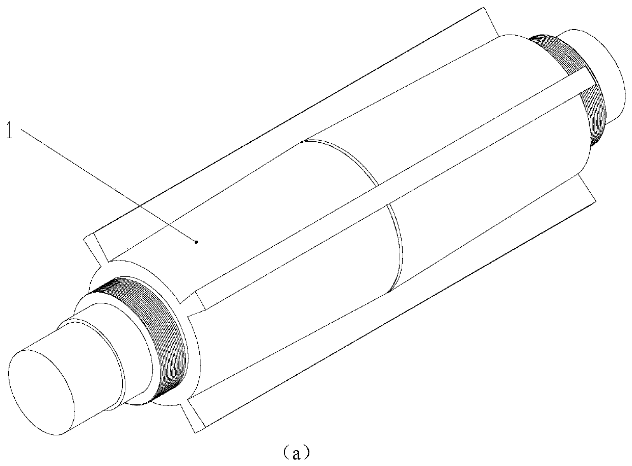
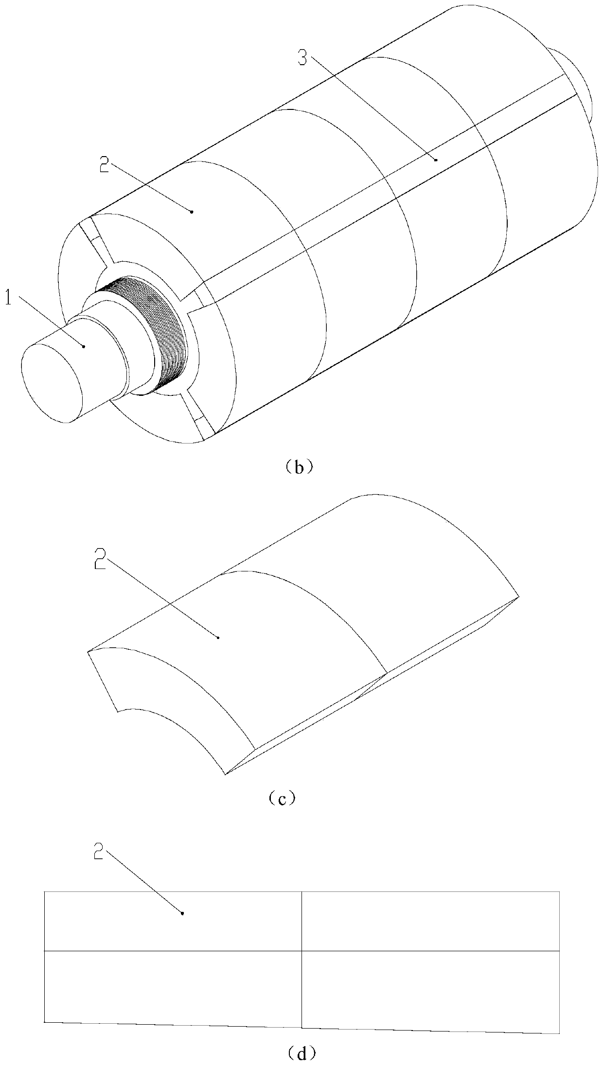
[0150] see figure 2 middle figure 2 a to figure 2 d illustrates this embodiment 2, the high-speed and high-power permanent magnet synchronous motor rotor described in this embodiment 2, including a rotating shaft 1, a conical main permanent magnet 2, an auxiliary permanent magnet 3, a preload nut and a sheath;

[0151] The rotating shaft 1 has a cylindrical structure, and its two ends are provided with external threads. The shaft body of the rotating shaft 1 in the circumferential direction is uniformly provided with P axial grooves, each axial groove includes two main permanent magnet embedding grooves, two The main permanent magnet embedding grooves are mirror-symmetrically arranged on the vertical plane of the length of the shaft body, and the depth of each main permanent magnet embedding groove gradually increases from the vertical plane to the end of the shaft body, so that the shaft body of the shaft 1 is in the It tapers toward its two ends; P is the number of pole...

Embodiment 3

[0167] see image 3 Describe this embodiment 3, the high-speed high-power permanent magnet synchronous motor rotor described in this embodiment 3 includes a rotating shaft 1, a conical main permanent magnet 2, an auxiliary permanent magnet 3, a positioning key 4, a preload nut and a sheath;

[0168] Rotating shaft 1 is a cylindrical body tapered at both ends, and both ends of rotating shaft 1 are provided with external threads, and 2P positioning key grooves are opened on the shaft of rotating shaft 1 along the axial direction, and P is the number of pole pairs of the motor;

[0169] The taper of the inner surface of the conical main permanent magnet 2 is the same as the taper of the shaft body of the rotating shaft 1;

[0170] A positioning key 4 is embedded in each positioning key groove, and 2k conical main permanent magnets 2 are arranged axially on the rotating shaft 1 between two adjacent positioning keys 4, where k is a positive integer;

[0171] The auxiliary permanen...


PUM


Abstract

The invention provides a high-speed high-power permanent magnet synchronous motor rotor, which belongs to the technical field of motors. The problems that the existing high-speed high-power permanentmagnet synchronous motor has difficulty in sheathing the sheath of the rotor and the prestress cannot be adjusted according to requirements are solved. The motor rotor mainly comprises a rotation shaft, a main permanent magnet, an auxiliary permanent magnet, a positioning key, a pre-tightened wedge, a pre-tightened nut and a sheath. The pre-tightened nut is used to axially squeeze a tapered or wedge-shaped device. According to the rotor diameter and the rotation speed, the prestress acting on the permanent magnets is radially flexibly adjusted. The rotor provided by the invention is mainly applied in the field of motors.

Description

technical field [0001] The invention belongs to the technical field of motors. Background technique [0002] Due to the high speed and high power density of high-speed motors, the geometric size of the motors is much smaller than that of low- and medium-speed motors of the same power, which has become a research hotspot in the field of motors. At present, the application fields of high-speed motors are becoming more and more extensive, such as high-speed grinding machines and other processing machine tools, high-speed flywheel energy storage systems, high-speed centrifugal compressors, blowers, and micro gas turbines for distributed power supply systems to drive high-speed generators. The permanent magnet synchronous motor is most suitable for high-speed motors because of its simple structure, high efficiency and power density, and no excitation loss. [0003] Under the condition of high-speed rotation of the traditional high-speed and high-power permanent magnet synchronou...

Claims


Application Information

Patent Timeline
IPC IPC(8): H02K1/27H02K1/28H02K21/12
CPCH02K1/27H02K1/274H02K1/28H02K21/12H02K2213/03
Inventor 寇宝泉杨小宝张赫李伟力
Owner HARBIN INST OF TECH
Why Eureka
Try Eureka