Permanent magnet motor remanufacturing and repairing process with magnetic poles glued and assembly line

A permanent magnet motor and remanufacturing technology, which is applied in the manufacture of motor generators, stator/rotor bodies, electrical components, etc., can solve the problems of magnetic pole residue, long time, etc., and achieve difficult oxidation and decarburization, small deformation, and realize cycle The effect of using

Active Publication Date: 2019-12-13
三立(厦门)汽车配件有限公司
View PDF6 Cites 3 Cited by
  • Summary
  • Abstract
  • Description
  • Claims
  • Application Information

AI Technical Summary

Problems solved by technology

The magnetic poles are fixed on the stator shell by glue. At present, a chisel is used to separate the magnetic poles from the stator shell, which takes a long time. At the same time, some magnetic poles remain on the stator shell and need to be removed by grinding.

Method used


Image

  • Permanent magnet motor remanufacturing and repairing process with magnetic poles glued and assembly line
  • Permanent magnet motor remanufacturing and repairing process with magnetic poles glued and assembly line
  • Permanent magnet motor remanufacturing and repairing process with magnetic poles glued and assembly line

Examples


Embodiment 1

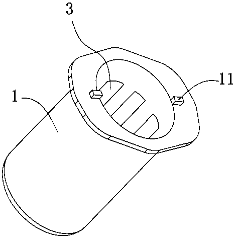
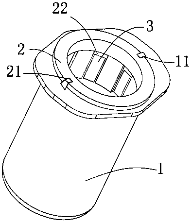
[0045] Such as Figure 4 As shown, this embodiment discloses a permanent magnet motor remanufacturing repair line with glued magnetic poles, including a heating device 7 , a rotating and fixing device 6 , a cooling pool 4 , a conveying device 5 , a knocking device 41 and an operating table 9 . The conveying device 5 is arranged obliquely in the cooling pool 4 , one end of the conveying device 5 is located in the cooling pool 4 , and one end extends out of the cooling pool 4 and is connected to one side of the operating platform 9 .

[0046] Such as Figure 7 As shown, the transmission device 5 includes a transmission motor 51, a transmission wheel 52 and a transmission belt 53, the transmission motor 51 and the transmission wheel 52 are arranged on both sides in the cooling pool 4, and the transmission belt 53 is installed on the transmission wheel 52 and the transmission motor 51. The conveyor belt 35 is evenly provided with several convex strips 54 , and the convex strips 5...

Embodiment 2

[0062] The difference between this embodiment and the first embodiment is that: Step 1: After taking out the rotor in the stator casing 1; cleaning the magnetic poles 3 in the stator casing 1, and detecting and identifying whether each magnetic pole 3 is damaged. Before detecting and identifying the magnetic pole 3 in the stator shell 1, it is sandblasted and cleaned, and the visual inspection system detects the outer surface of the magnetic pole 3 after sand blasting to check whether there are cracks, depressions and other adverse conditions on the appearance of the magnetic pole 3 .

[0063] The damaged magnetic poles are marked and classified, and the stator shell is divided into several heating areas and cooling areas. The surface of the stator shell corresponding to the damaged magnetic poles is the heating area, and the surface of the stator shell corresponding to the undamaged magnetic poles is the cooling area. Such as Figure 5 As shown, put the stator housing 1 into...


PUM


Abstract

The invention discloses a permanent magnet motor remanufacturing and repairing process with magnetic poles glued and an assembly line. The process comprises the following steps: firstly, the end coverof a to-be-repaired permanent magnet motor is opened, the outer surface of a stator shell is heated until glue is melted and fails, magnetic poles on the inner side of the stator shell are beaten, and the magnetic poles are separated from the stator shell; the stator shell after being separated is cooled, and glue is adhered to the surface, in contact with the stator shell, of a new magnetic pole; and the surfaces of the positive magnetic pole and the negative magnetic pole which are adhered with the glue are alternately glued to the inner wall of the stator shell. The invention further discloses a permanent magnet motor remanufacturing and repairing assembly line with the magnetic poles glued, which comprises a rotary fixing device, a heating device, a cooling pool, a conveying device and an operation table. The magnetic pole and the stator shell can be completely separated, the magnetic pole is prevented from remaining in the stator shell, the stator shell is not damaged, and the remanufacturing production of the permanent magnet motor is realized.

Description

technical field [0001] The invention relates to the technical field of repairing a permanent magnet motor, in particular to a remanufacturing and repairing process and assembly line of a permanent magnet motor with glued magnetic poles. Background technique [0002] In the current remanufacturing process of permanent magnet motors, it is necessary to disassemble and replace the damaged and invalid magnetic poles of the permanent magnet motor. In the process of remanufacturing, the damaged and invalid magnetic poles need to be disassembled from the stator shell Replace the poles before reinstalling the stator housing. The magnetic poles are fixed on the stator housing by glue. At present, a chisel is used to separate the magnetic poles from the stator housing, which takes a long time. At the same time, some magnetic poles remain on the stator housing and need to be removed by grinding. Contents of the invention [0003] The purpose of the present invention is to provide a ...

Claims


Application Information

Patent Timeline
Patent Type & Authority Applications(China)
IPC IPC(8): H02K15/03
CPCH02K15/03
Inventor 吴冬鸣黄裕梗林卫平李宪国刘小平
Owner 三立(厦门)汽车配件有限公司
Why Eureka
Try Eureka