Ectopic remediation device for high-temperature gas heating remediation of soil
A technology for repairing soil and high-temperature gas, applied in the field of soil repair, can solve the problems of large thermal desorption equipment, large floor space, large energy consumption, and high cost, and achieve the effect of reducing manual labor and simplifying the process
- Summary
- Abstract
- Description
- Claims
- Application Information
AI Technical Summary
Problems solved by technology
Method used
Image

Examples
Embodiment 1
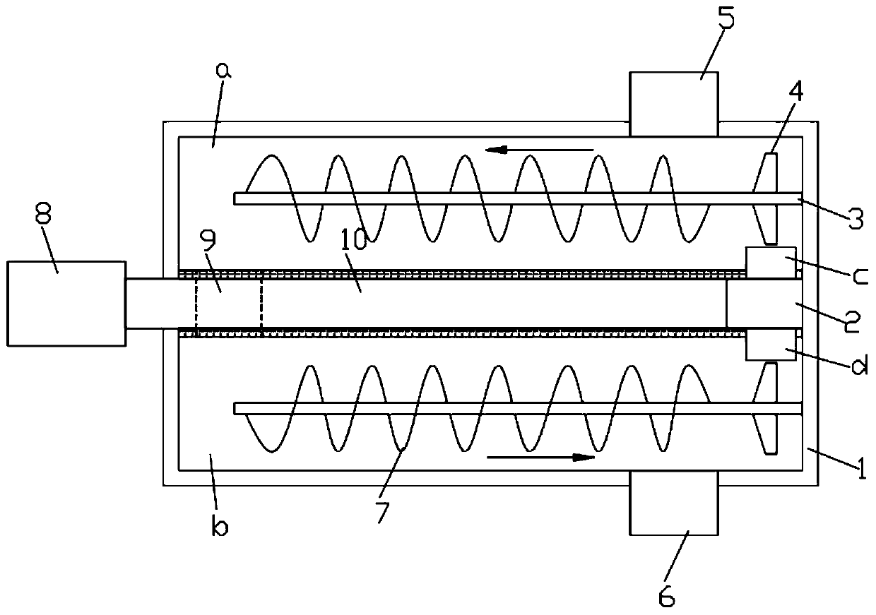
[0024] refer to figure 1 , a kind of heterotopic restoration device for heating and repairing soil with high-temperature gas, comprising a box body 1, a feeding nozzle 5 arranged at the upper end of the box body 1, and a discharge nozzle 6 arranged at the lower end of the box body 1, and a horizontal edge is arranged in the box body 1 The heat insulation board arranged in the direction, the heat insulation board divides the box body 1 into a heating chamber located in the upper half and a cooling chamber located in the lower half. One end of 10 runs through the inner wall of the box body 1 and is equipped with an air compressor 8. A vortex tube 2 is installed on the heat shield, and the input end of the vortex tube 2 communicates with the output end of the air duct 10, and the hot gas output end of the vortex tube 2 The cold air output end of the vortex tube 2 penetrates the heat insulation board and extends into the cooling chamber. The box body 1 is located on the inner wall...
Embodiment 2
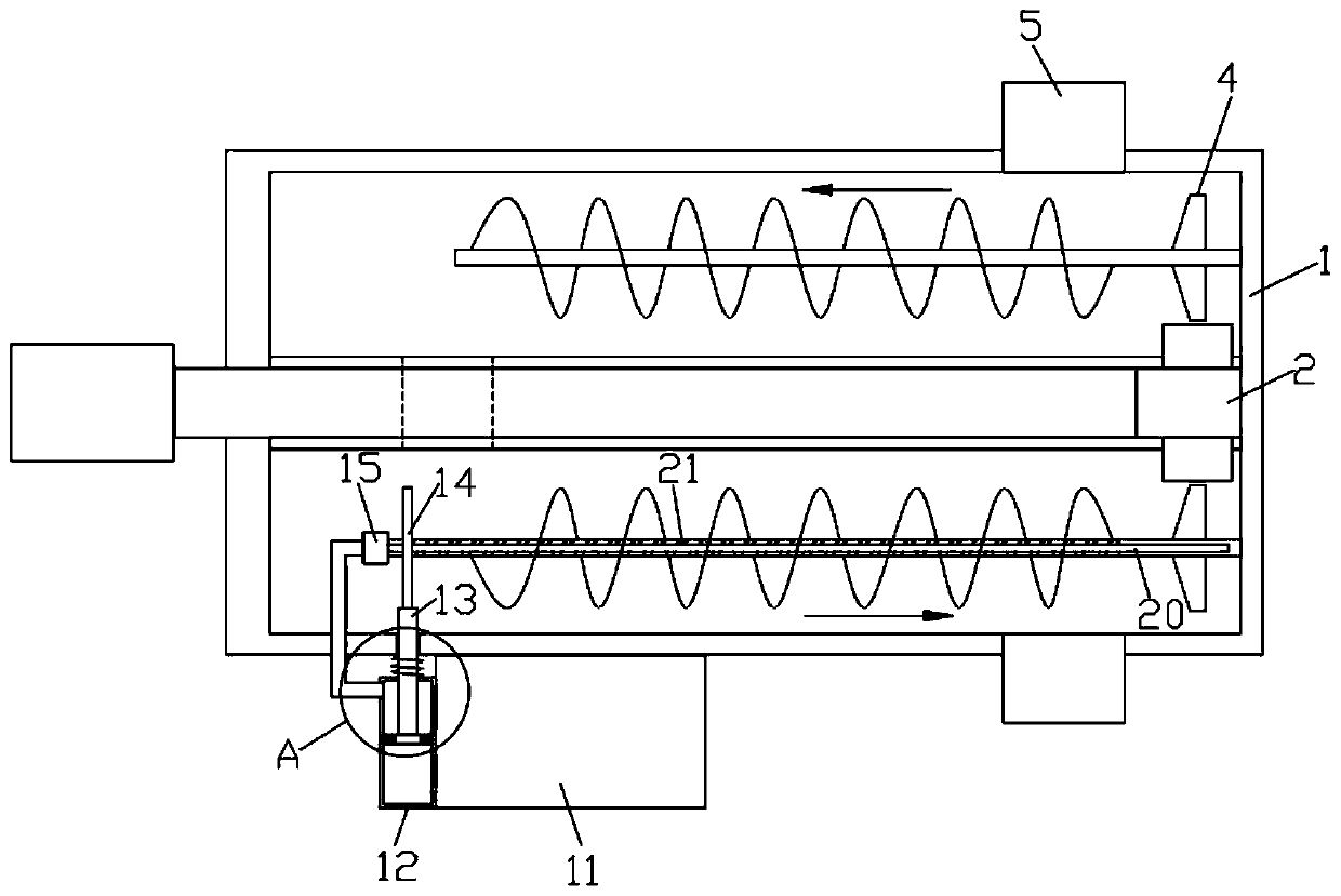
[0027] refer to Figure 2-3 The rotating shaft 3 located in the cooling chamber is provided with a water delivery chamber 20 along its radial direction, the surface of the rotating shaft 3 is evenly distributed with drainage micro-holes 21 communicating with the water delivery chamber 20, and the lower end of the box body 1 is fixedly connected with a liquid storage tank 11 , the side wall of the liquid storage tank 11 is installed with a pumping device for pumping the bacteria solution in the liquid storage tank 11 into the water delivery chamber 20 .
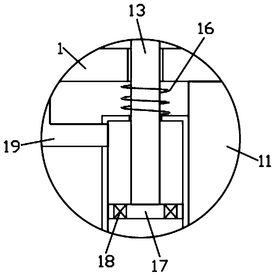
[0028] The liquid pumping device includes a sliding plug tube 12 fixedly connected to the side wall of the liquid storage tank 11, the lower end of the sliding plug tube 12 communicates with the liquid storage tank 11, and a device is installed at the connection to only allow the bacterial liquid to enter from the liquid storage tank 11 into the The first one-way valve in the slide barrel 12 is sealed and slidably connected wi...
PUM
 Abstract
Description
Claims
Application Information
 - Generate Ideas
- Intellectual Property
- Life Sciences
- Materials
- Tech Scout
- Unparalleled Data Quality
- Higher Quality Content
- 60% Fewer Hallucinations
Browse by: Latest US Patents, China's latest patents, Technical Efficacy Thesaurus, Application Domain, Technology Topic, Popular Technical Reports.
© 2025 PatSnap. All rights reserved.Legal|Privacy policy|Modern Slavery Act Transparency Statement|Sitemap|About US| Contact US: help@patsnap.com