Common-beam scanning retina imaging system

A beam scanning and imaging system technology, applied in the field of optical imaging, can solve the problems of inability to observe lesions with a large field of view, small imaging field of view, and insufficient resolution to observe the microstructure of the retina

Active Publication Date: 2019-12-20
SUZHOU INST OF BIOMEDICAL ENG & TECH CHINESE ACADEMY OF SCI
View PDF18 Cites 8 Cited by
  • Summary
  • Abstract
  • Description
  • Claims
  • Application Information

AI Technical Summary

Problems solved by technology

However, the device can only achieve high-resolution imaging with a maximum 3-degree field of view of the human eye
Limited by the halo area of ​​adaptive optics aberration correction, adaptive optics often compromises on the imaging field of view while achieving high-resolution imaging, and can only achieve small field of view imaging within 3°
[0004] In summary, the existing laser co

Method used


Image

  • Common-beam scanning retina imaging system
  • Common-beam scanning retina imaging system
  • Common-beam scanning retina imaging system

Examples


Embodiment Construction

[0054] The present invention will be further described in detail below in conjunction with the embodiments, so that those skilled in the art can implement it with reference to the description.

[0055] It should be understood that terms such as "having", "comprising" and "including" used herein do not exclude the presence or addition of one or more other elements or combinations thereof.

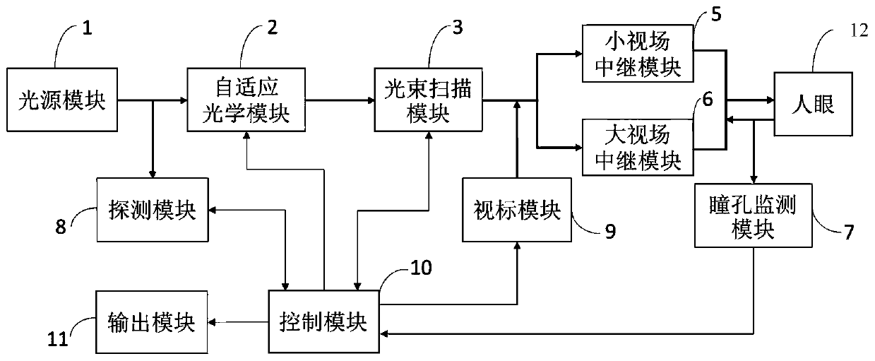
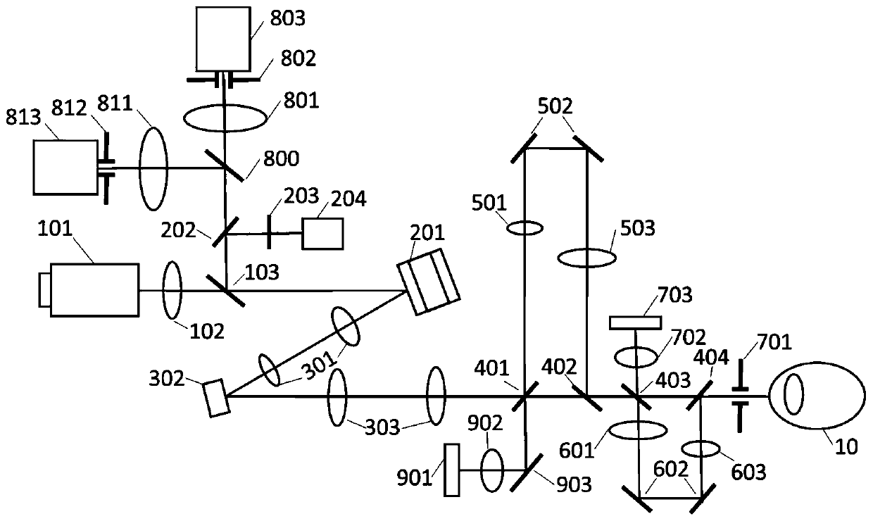
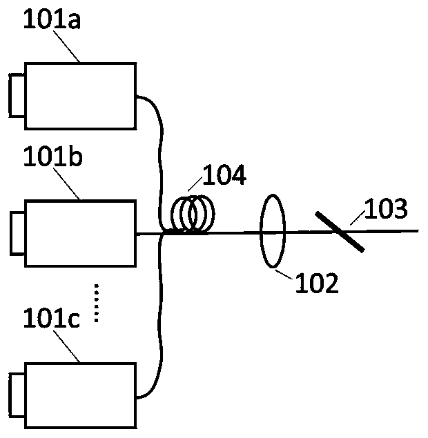
[0056] Such as Figure 1-2 As shown, a common beam scanning retinal imaging system of this embodiment includes: a light source module 1, an adaptive optics module 2, a beam scanning module 3, a small field of view relay module 5, a large field of view relay module 6, a field of view Standard module 9, pupil monitoring module 7, detection module 8, control module 10 and output module 11;

[0057] The light source module 1 can emit parallel light beams of at least two different wavelengths. The parallel light beams sequentially pass through the adaptive optics module 2, the beam scanning modu...


PUM


Abstract

The invention discloses a common-beam scanning retina imaging system which comprises a light source module, a self-adaptive optical module, a beam scanning module, a small-view-field relay module, a large-view-field relay module, a sighting mark module, a pupil monitoring module, a detection module, a control module and an output module. According to the system, human eye aberration is corrected in real time by using an adaptive optical technology, and a confocal scanning imaging function in a large view field range and an adaptive optical high-resolution imaging function in a small view fieldrange can be simultaneously realized through light beam synchronous scanning setting in combination with two sets of relay light path structures of the small view field and the large view field. According to the system, a large-range disease focus area of a retina can be observed through large-view-field imaging, a fine structure of a focus can be observed through small-view-field high-resolutionimaging, various imaging images are obtained through common-light-path light beam scanning, different application scene requirements are met, and the application range of existing confocal imaging equipment is greatly expanded.

Description

technical field [0001] The invention relates to the technical field of optical imaging, in particular to a common beam scanning retinal imaging system. Background technique [0002] The traditional confocal scanning technology developed into a mature laser confocal scanning imaging device in 1987 (Webb R, Hughes G, Delori F. Confocal scanning laser ophthalmoscope. Applied optics. 1987; 26(8): 1492-9), And it is widely used in retinal imaging, which can realize in vivo fundus retinal imaging with a large field of view. However, the eyeball is a complex optical system, even the eyes with no refractive error will inevitably have optical aberrations, especially in order to obtain high resolution under large numerical aperture, under the large pupil according to optical theory can get better High diffraction-limited resolution, but the large pupil brings more aberrations of the human eye, which greatly limits the actual resolution. Traditional laser confocal scanning ophthalmosc...

Claims


Application Information

Patent Timeline
IPC IPC(8): A61B3/12A61B3/14
CPCA61B3/12A61B3/14A61B3/152A61B3/112A61B3/1025A61B3/1015A61B3/113G02B21/0028G02B21/0032G02B21/008G02B21/18G02B21/0012A61B3/0091
Inventor 何益史国华高峰孔文邢利娜李婉越王晶张欣
Owner SUZHOU INST OF BIOMEDICAL ENG & TECH CHINESE ACADEMY OF SCI
Why Eureka
Try Eureka