Unlock instant, AI-driven research and patent intelligence for your innovation.

Manufacturing method of ink overflow prevention structure

A production method and anti-overflow technology, which are applied to the device for coating liquid on the surface, pre-treatment surface, coating, etc., can solve the problem of easy to overflow ink, so as to reduce the overflow of ink, reduce production cost, and increase production. The effect of efficiency and mass production yield

Pending Publication Date: 2019-12-20
ZHEJIANG SUNNY OPTICAL CO LTD
View PDF2 Cites 0 Cited by
  • Summary
  • Abstract
  • Description
  • Claims
  • Application Information

AI Technical Summary

Problems solved by technology

[0004] The main purpose of the present invention is to provide a method for making an anti-spill structure, so as to solve the problem of ink spill easily occurring in the process of ink coating of optical lenses in the prior art

Method used


Image

  • Manufacturing method of ink overflow prevention structure
  • Manufacturing method of ink overflow prevention structure
  • Manufacturing method of ink overflow prevention structure

Examples


Embodiment 1

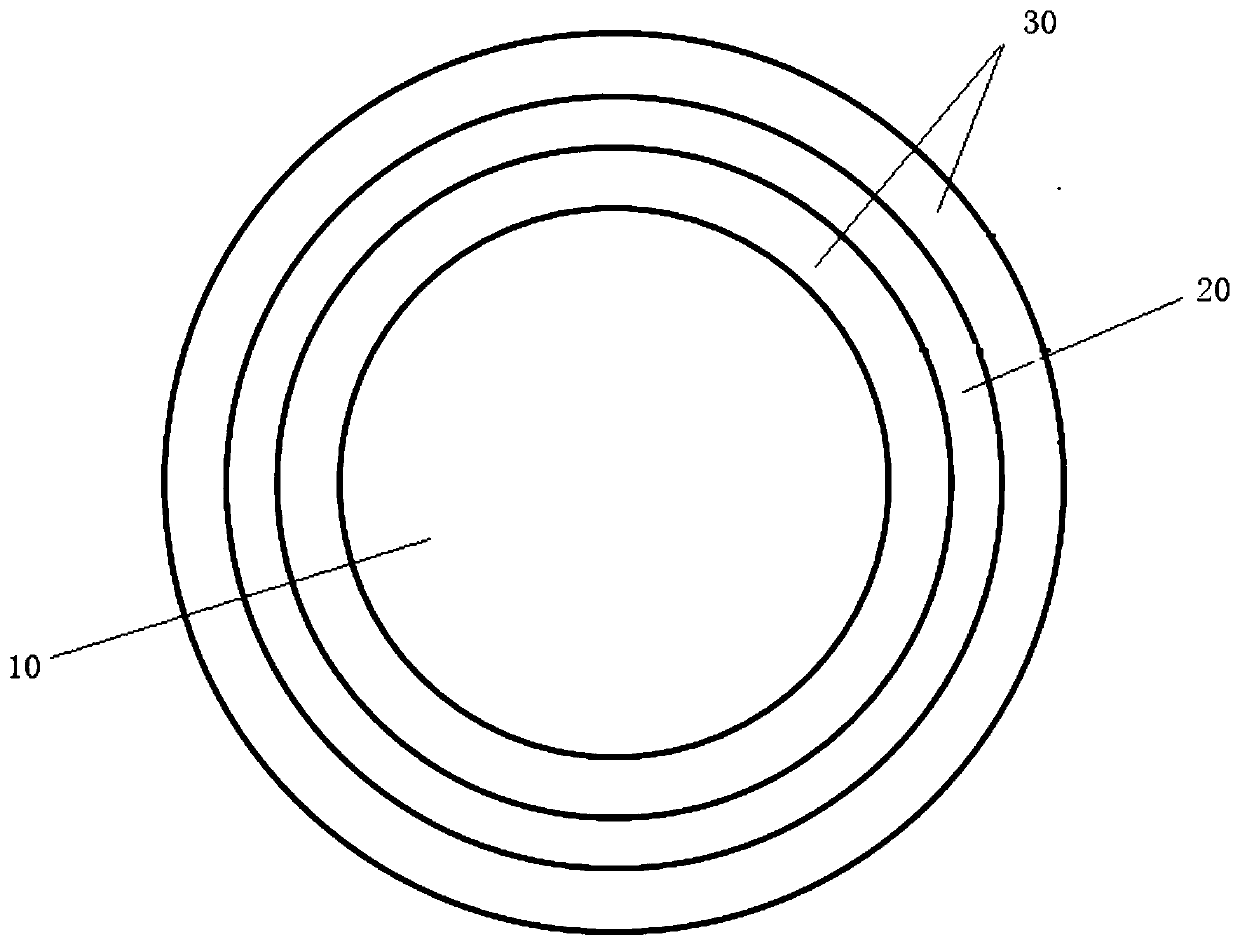
[0037] Such as Figure 1 to Figure 3 As shown, the manufacturing method of the anti-spill ink structure includes: the area 20 to be blocked in the optically inactive area in the optical lens is blocked, wherein the area of ​​the area to be blocked 20 is greater than 1 / 2 of the area of ​​the optically ineffective area; Scan the area except the area 20 to be shielded with the laser beam; heat the optical lens; and cool the optical lens.

[0038] The hydrophilicity or hydrophobicity of the scanning area 30 is changed by scanning the optical lens with the laser beam, so that the hydrophilicity of the ink-coated area is greater than that of the area adjacent to the ink-coated area, thereby reducing the tendency of the ink-coated area to Spilled ink greatly increases the accuracy of ink coating on optical lenses, increases the production efficiency and mass production yield of optical imaging lenses, and reduces production costs. Heating the optical lens can increase the periodicit...

Embodiment 2

[0060] Such as Figure 4 As shown, the manufacturing method of the anti-spill ink structure includes: the to-be-shielded area 20 of the optically inactive area in the optical lens is blocked, wherein, the area of ​​the to-be-shielded area 20 is less than one-half of the area of ​​the optically ineffective area; Scan the area except the area 20 to be shielded with the laser beam; heat the optical lens; and cool the optical lens.

[0061] The hydrophilicity or hydrophobicity of the scanning area 30 is changed by scanning the optical lens with the laser beam, so that the hydrophilicity of the ink-coated area is greater than that of the area adjacent to the ink-coated area, thereby reducing the tendency of the ink-coated area to Spilled ink greatly increases the accuracy of ink coating on optical lenses, increases the production efficiency and mass production yield of optical lenses, and reduces production costs. Heating the optical lens can increase the periodicity of the surfac...


PUM

PropertyMeasurementUnit
Wavelengthaaaaaaaaaa

Abstract

The invention provides a manufacturing method of an ink overflow prevention structure. The manufacturing method of the ink overflow prevention structure comprises the following steps: shielding a to-be-shielded area of an optically invalid area in an optical lens, wherein the area of the to-be-shielded area is larger than half of the area of the optically invalid area; performing laser beam scanning on areas other than the to-be-shielded area of the optically invalid area; heating the optical lens; and cooling the optical lens. By adopting the ink overflow prevention structure provided by theinvention, the problem that ink overflow easily occurs in the process of applying ink to optical lenses in the prior art can be solved.

Description

technical field [0001] The invention relates to the technical field of optical imaging equipment, in particular to a method for manufacturing an anti-overflow structure. Background technique [0002] At present, the field of optical imaging lenses used in mobile phones needs to use miniaturized optical lenses on the order of millimeters, and these optical lenses need to have an optically effective part for transmitting light and a support for bearing during assembly. Optically ineffective part. The reflection and scattering of light in the optically ineffective part will generate various stray light and produce stray light imaging on the imaging sensor that affects the imaging quality. In order to suppress stray light imaging, it is necessary to perform light absorption processes such as ink coating on the optically ineffective part to reduce the generation of stray light. Good inking improves both image quality and lens appearance. At present, the inking process is mostl...

Claims


Application Information

Patent Timeline
IPC IPC(8): B05D5/00B05D3/00B05D3/02B05D3/04B05D7/24B05D1/32
CPCB05D1/32B05D3/002B05D3/0218B05D3/0426B05D5/00B05D7/24B05D2203/35
Inventor 杨萌徐春慧戴付建赵烈烽
Owner ZHEJIANG SUNNY OPTICAL CO LTD
Features
  • R&D
  • Intellectual Property
  • Life Sciences
  • Materials
  • Tech Scout
  • Unparalleled Data Quality
  • Higher Quality Content
  • 60% Fewer Hallucinations
Learn More