Control system for service robot
A service robot and control system technology, applied in the direction of program control manipulators, manipulators, manufacturing tools, etc., can solve the problems of low robot operation stability, service robot design, high production cost, reduce performance, improve operation stability, and facilitate design effect
- Summary
- Abstract
- Description
- Claims
- Application Information
AI Technical Summary
Problems solved by technology
Method used
Image

Examples
Embodiment 1
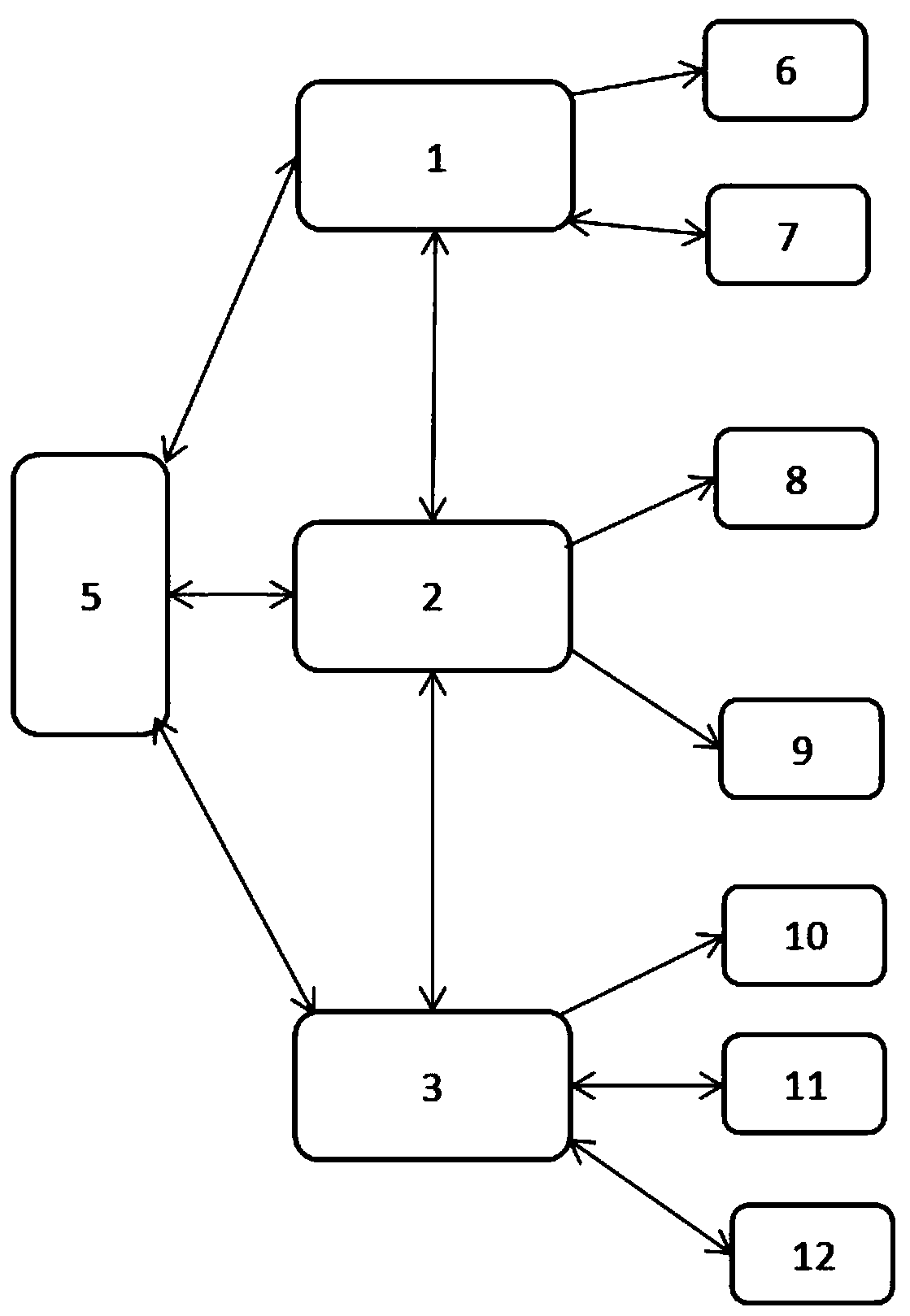
[0024] Refer to attached Figure 1-2 , this embodiment provides a control system for a service robot, including an upper control module 1, a middle control module 2, a bottom control module 3, and a motion module for driving the robot to perform activities, and the motion module includes a head drive mechanism 6. Waist driving mechanism 7, arm driving mechanism 8 and foot driving mechanism 11; the upper control module 1 is the existing STM32F205 single-chip microcomputer, the middle control module 2 is the existing STM32F427 single-chip microcomputer, and the bottom control module 3 is the existing STM32F205 single-chip microcomputer .
[0025] Wherein, the head drive mechanism 6 and the waist drive mechanism 7 are electrically connected to the upper control module 1 through the RS485 interface, and the arm drive mechanism 8 is electrically connected to the middle control module 2 through the RS485 interface. The foot drive mechanism 11 is electrically connected to the bottom...
Embodiment 2
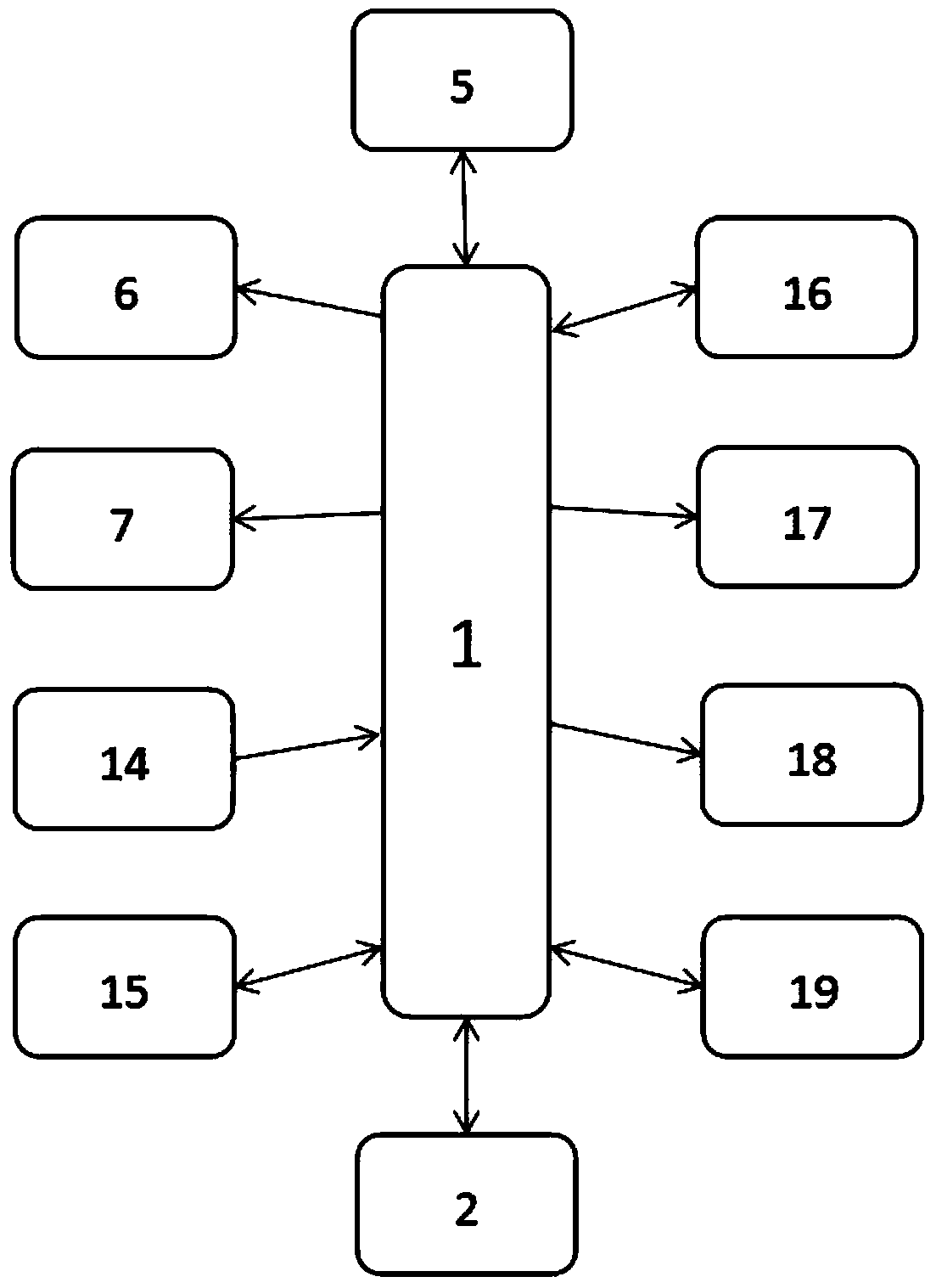
[0030] Refer to attached image 3 , this embodiment provides a specific control structure of the middle control module 2 on the basis of embodiment 1. Specifically, the middle control module 2 communicates with the PIR module 9, the touch sensor module 14, and the heat dissipation module respectively through GPIO. Module 18, wired controller 20, inverter module 21, power amplifier module 22, electronic lock 23 and RGB LED are electrically connected; PIR module 9 is a passive infrared detector (Passive Infrared Detector, PIR) in the prior art, Through the high and low level changes generated by the PIR module 9, it is judged whether there are people or other creatures in front of the robot; the wired controller 20 is used for external keyboards and other equipment, so as to control the robot to perform operations such as forward, backward, left, right, and stop; the inverter The module 21 includes a code switch, and there are two code switches, and its input pin is electrically...
Embodiment 3
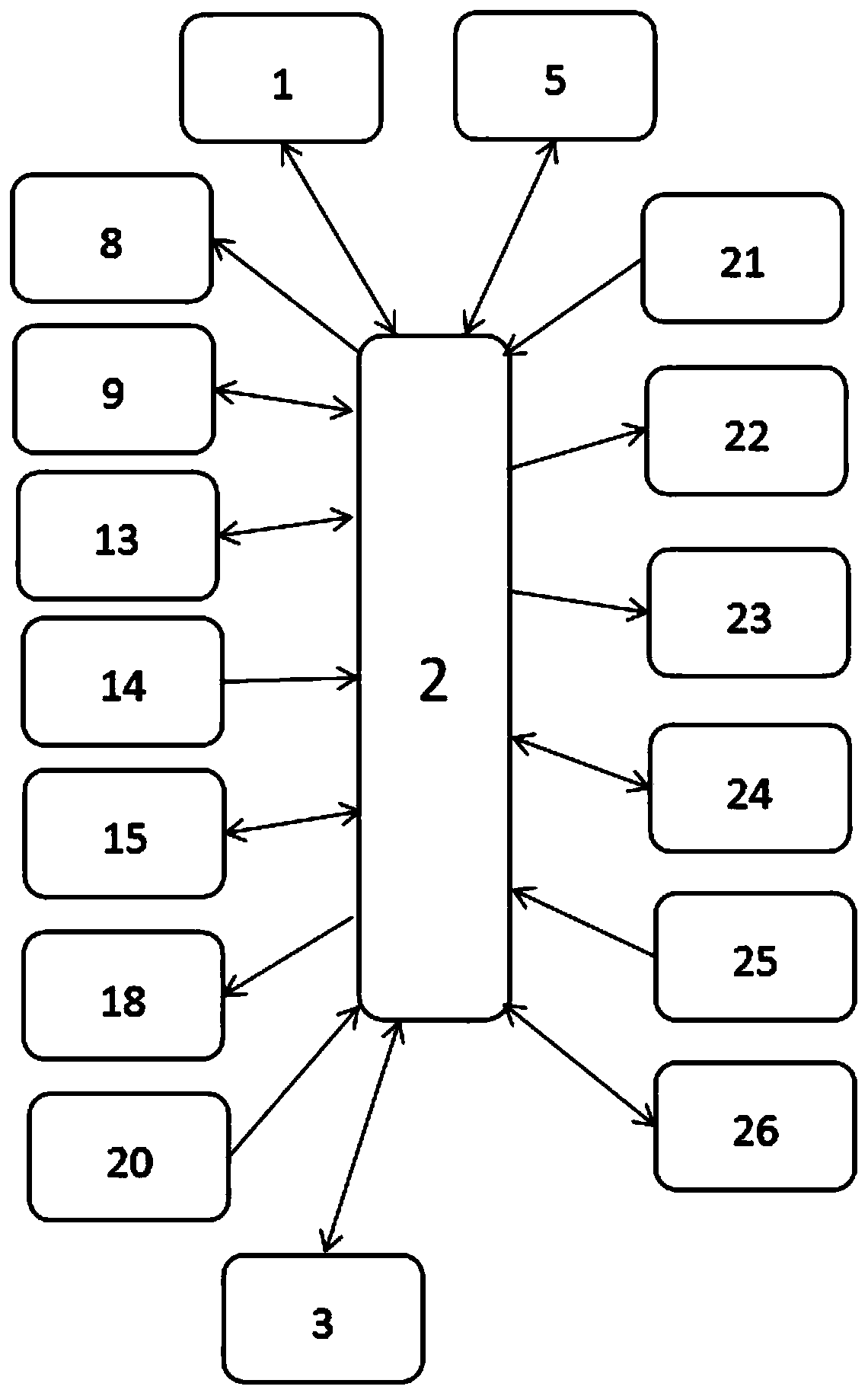
[0033] Refer to attached Figure 4 , this embodiment provides a specific control structure of the bottom control module 3 on the basis of the embodiment 1-2. Specifically, the bottom control module 3 is also connected with the key module 27 and the heat dissipation module 18 through GPIO respectively. , inverter module 21, reset module 28, power supply module 29 and visual camera module 10 are electrically connected; button module 27 includes five buttons on the back of the robot to realize the front, rear, left, right, and stop of the robot. Operation; the inverter module 21 includes an output pin, which controls the on / off of the inverter through high and low levels, and is initialized to the shutdown state after starting up, and the bottom control module 3 queries the middle control module 2 for the dial code of the inverter through this Switch state, carry out corresponding switch operation according to the state found; Reset module 28 can reset network switch according to...
PUM
 Abstract
Description
Claims
Application Information
PatSnap Eureka turns technology decisions into work you can execute. Powered by our Innovation Knowledge Graph, it runs expert workflows across engineering, life sciences, materials and intellectual property. Get your review-ready output in minutes.


