Printing device used for spinning

A technology for printing devices and printing blocks, applied in printing devices, printing, printing machines, etc., can solve the problems of difficult automatic control, increased capital cost, complex structure, etc., and achieve automatic control, increase productivity, and reasonable structural design Effect

Inactive Publication Date: 2019-12-20
徐州第三纺织有限公司
View PDF0 Cites 3 Cited by
  • Summary
  • Abstract
  • Description
  • Claims
  • Application Information

AI Technical Summary

Problems solved by technology

Most of the current textile printing devices have complex structures and are not easy to realize automatic control, and the printed textiles are stacked randomly, which may cause wrinkles and indentations, which is easy to cause waste and increase capital costs

Method used


Image

  • Printing device used for spinning
  • Printing device used for spinning
  • Printing device used for spinning

Examples


Embodiment Construction

[0016] In order to make the content of the present invention easier to be understood clearly, the technical solutions in the embodiments of the present invention will be described clearly and completely in conjunction with the accompanying drawings in the embodiments of the present invention.

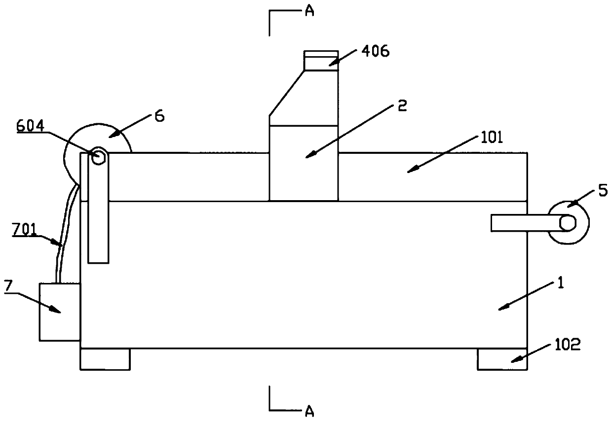
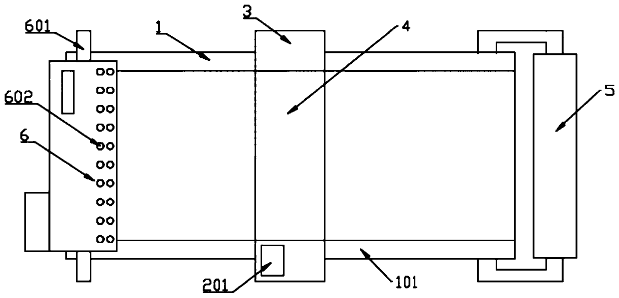
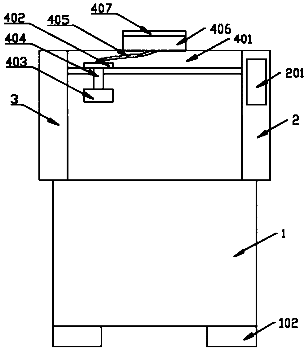
[0017] Such as Figure 1-Figure 3 As shown, a textile printing device includes a base 1, a support, a printing module 4, a feed roller 5, and a winding roller 6. The base 1 is provided with baffles 101 on both sides, and the bottom of the base is provided with legs 102. The bracket includes bracket 1 2 and bracket 2 3 respectively fixedly connected to both sides of the base 1, a printing module 4 is arranged between bracket 1 2 and bracket 2 3, and a controller and a battery electrically connected are arranged inside bracket 1 2. A control panel 201 is fixedly connected to the top of the bracket 2, and the control panel 201 is electrically connected to the controller;

[0018] The printing ...


PUM


Abstract

The invention relates to a spinning tool and discloses a printing device used for spinning. The printing device comprises a base, supports, a printing module, a feeding roller and a rolling roller. The supports include the first support and the second support fixedly connected to the two sides of the base correspondingly. The printing module is arranged between the first support and the second support. A controller and a battery which are connected electrically are arranged in the first support. A control panel is fixedly connected to the top of the first support. The printing module comprisesa sliding groove, a sliding block and a coating box, a control block is arranged in the sliding groove, the printing block is connected to the control block through a telescopic rod, and the printingblock is connected to the coating box through a spraying pipe. The feeding roller and the rolling roller are arranged at the two ends of the base correspondingly. A drying hole is formed in one sideof the rolling roller, a gas expansion shaft is arranged in the center of the rolling roller, and the gas expansion shaft is connected with a hot air box through a connecting pipe. The printing deviceis reasonable in structural design, fixing and drying are facilitated, textiles obtained after printing are ironed flatly, productivity is effectively improved, the labor intensity is lowered, and the printing device meets the need for large-scale production and also meets the requirement for cleanliness and sanitation.

Description

Technical field [0001] The invention relates to textile appliances, in particular to a textile printing device. Background technique [0002] With the continuous improvement of people's living standards, the requirements for textile printing are getting higher and higher, and the demand for new technology development of textile pattern printing technology is becoming stronger. Most of the current textile printing devices have complex structures and are not easy to realize automatic control. Moreover, the printed textiles are randomly stacked, which may cause wrinkles and indentations, which is easy to cause waste and increase capital costs. Summary of the invention [0003] In view of the above-mentioned shortcomings in the prior art, the present invention provides a textile printing device, which has a simple structure and is convenient for popularization. [0004] In order to achieve the above-mentioned purpose of the invention, the technical solution adopted by the invention is:...

Claims


Application Information

Patent Timeline
Patent Type & Authority Applications(China)
IPC IPC(8): B41F17/00B41F23/04B41F33/00
CPCB41F17/003B41F23/0426B41F33/00B41P2217/50
Inventor 李孝同郝成生
Owner 徐州第三纺织有限公司
Why Eureka
Try Eureka