Urban rail train vehicle-mounted energy storage system control method based on power-time curve

An urban rail train, time curve technology, applied in vehicle energy storage, electric braking system, battery/fuel cell control device, etc., can solve the problem of low utilization rate of vehicle hybrid energy storage device, reduced braking power, environmental problems Temperature rise and other problems, to achieve the effect of reducing power shock, reducing heat dissipation, and absorbing power

Active Publication Date: 2019-12-20
SHENZHEN LOTUT INNOVATION DESIGN CO LTD
View PDF5 Cites 3 Cited by
  • Summary
  • Abstract
  • Description
  • Claims
  • Application Information

AI Technical Summary

Problems solved by technology

[0003] The existing problems are: firstly, during the braking process of the train, as the running speed decreases, its braking power is a dynamic and gradually decreasing process
At this time, the first-order low-pass filter energy distribution method with a fixed cut-off frequency is adopted. Due to the small idle capacity of the supercapacitor, the corresponding braking energy can only be absorbed in a small amount, and the unabsorbed energy can only be absorbed by the resistance energy dissipation device The heat is dissipated in the form of heat; although the battery has a large idle capacity, it is limited by the charging power due to its low power density. At this time, the braking power is relatively large, and it may absorb a certain amount of braking energy. It is still not fully charged, which not only makes the utilization rate of the on-board hybrid energy storage device not high, but also the unnecessary heat dissipation of the resistive energy-consuming device will also affect the increase of the ambient temperature of the on-board hybrid energy storage device, causing a burden on the temperature control system

Method used


Image

  • Urban rail train vehicle-mounted energy storage system control method based on power-time curve
  • Urban rail train vehicle-mounted energy storage system control method based on power-time curve
  • Urban rail train vehicle-mounted energy storage system control method based on power-time curve

Examples


Embodiment Construction

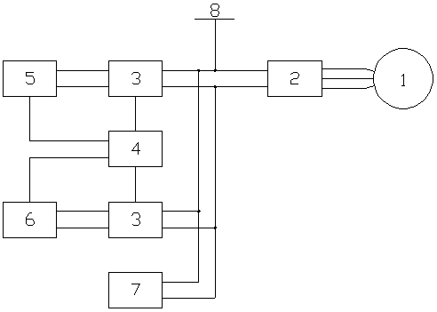
[0028] A control method for an on-board energy storage system of an urban rail train based on a power-time curve. The on-board energy storage system of an urban rail train includes a traction motor 1, a four-quadrant inverter 2, two bidirectional DC-DC converters 3, and a control Module 4, storage battery 5, supercapacitor 6, resistive energy consumption device 7 and catenary 8;

[0029] The input end of the traction motor 1 is connected to the three-phase connection end of the four-quadrant inverter 2; the DC end of the four-quadrant inverter 2 is connected to the catenary 8, and at the same time, the DC end of the four-quadrant inverter 2 passes through the first A bidirectional DC-DC converter 3 is connected to the storage battery 5. At the same time, the DC terminal of the four-quadrant inverter 2 is connected to the supercapacitor 6 through the second bidirectional DC-DC converter 3. At the same time, the DC terminal of the four-quadrant inverter 2 The terminal is connect...


PUM


Abstract

The invention provides an urban rail train vehicle-mounted energy storage system control method based on power-time curve. The urban rail train vehicle-mounted energy storage system comprises a traction motor, a four-quadrant inverter, two bidirectional DC-DC converters, a control module, a storage battery, a super capacitor, a resistance energy dissipation device and a catenary; in the control method, the double-cut-off frequency is adopted to control the charging action of the storage battery and the super capacitor. The urban rail train vehicle-mounted energy storage system control method has the beneficial technical effects that the urban rail train vehicle-mounted energy storage system control method based on the power-time curve is proposed, according to the scheme, the control method can fully play the advantages of high super capacitor absorption efficiency and large absorption power, reduce the power impact to the storage battery, improve the performance of the hybrid energy storage system, and reduce unnecessary heat dissipation.

Description

technical field [0001] The invention relates to a braking energy recovery technology for urban rail trains, in particular to a control method for an on-board energy storage system of urban rail trains based on a power-time curve. Background technique [0002] In order to recover and utilize the braking energy of urban rail trains, the most common method is to install a vehicle-mounted hybrid energy storage device on the urban rail train. The vehicle-mounted hybrid energy storage device usually adopts a "super capacitor + battery" structure. During the braking process of the urban rail train, the traction motor works in the power generation state, converting the kinetic energy of the vehicle into electrical energy. At the same time, a first-order low-pass filter is used to decompose the power of train regenerative braking into high-frequency components and low-frequency components, thereby generating corresponding power control signals, and controlling the bidirectional DC-DC...

Claims


Application Information

Patent Timeline
Patent Type & Authority Applications(China)
IPC IPC(8): B60L7/16B60L58/12B60L50/53
CPCB60L7/16B60L58/12B60L50/53Y02T30/00
Inventor 徐凯陈臻涂永超杨锐李伟吴仕勋
Owner SHENZHEN LOTUT INNOVATION DESIGN CO LTD
Why Eureka
Try Eureka