Full-aluminum alloy material van carriage and manufacturing process

A van truck and manufacturing process technology, which is applied to the upper structure of the truck, vehicle components, upper structure, etc., can solve the problems of weak overall strength of the composite material carriage, affecting the mileage of pure electric trucks, and high maintenance costs of the carriage. Achieve the effects of a wide range of appearance color options, improved stability and safety performance, good corrosion resistance and weather resistance

Inactive Publication Date: 2019-12-20
方大新材料(江西)有限公司
8 Cites 4 Cited by

AI-Extracted Technical Summary

Problems solved by technology

[0003] At present, the compartments of vans are still mainly made of steel, and there are also van compartments made of composite materials such as fiberboards and honeycomb panels. If pure electric vans continue to use steel compartments, first of all, the weight reduction cannot be achieved. Demand will greatly affect the cruising range of pure electric trucks. On the other hand, the steel carriages are prone to corrosion after long...

Abstract

The invention discloses a full-aluminum alloy material van carriage and a manufacturing process thereof. The all-aluminum alloy material van carriage comprises a bottom plate assembly, a top plate assembly, a left side plate assembly, a right side plate assembly, a rear door assembly and a front side plate assembly; each sub-assembly is processed separately to form a modular unit, and finally assembly molding of the carriage is completed on the assembly line; the whole frame of the carriage adopts a 6063T6 material aluminum alloy extruded profile, the profile is machined through milling and stamping by a special die to achieve the required state of assembling; assembling of the carriage frame adopts the assembly process of BOOM structure rivet riveting, argon arc welding and bolt connection combination to obtain a frame structure with high strength and good stability; a panel structure of the carriage adopts a 5052 material high-strength aluminum alloy single-layer plate, and the plateis manufactured through a sheet metal machining process such as blanking, punching, bending, argon welding, grinding and the like; and high-gloss powder spraying treatment is adopted on the outer surface of the whole carriage. According to the van carriage and the manufacturing process, the purpose of lightweight of the vehicle body is achieved by adopting the all-aluminum alloy material.

Application Domain

Technology Topic

Image

  • Full-aluminum alloy material van carriage and manufacturing process
  • Full-aluminum alloy material van carriage and manufacturing process
  • Full-aluminum alloy material van carriage and manufacturing process

Examples

  • Experimental program(1)

Example Embodiment

[0027] In order to make it easy to understand the technical means, creative features, goals and effects achieved by the present invention, the present invention will be further explained below in conjunction with specific embodiments and drawings.
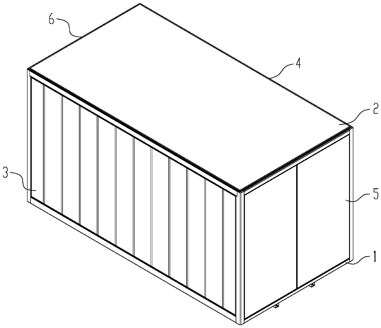
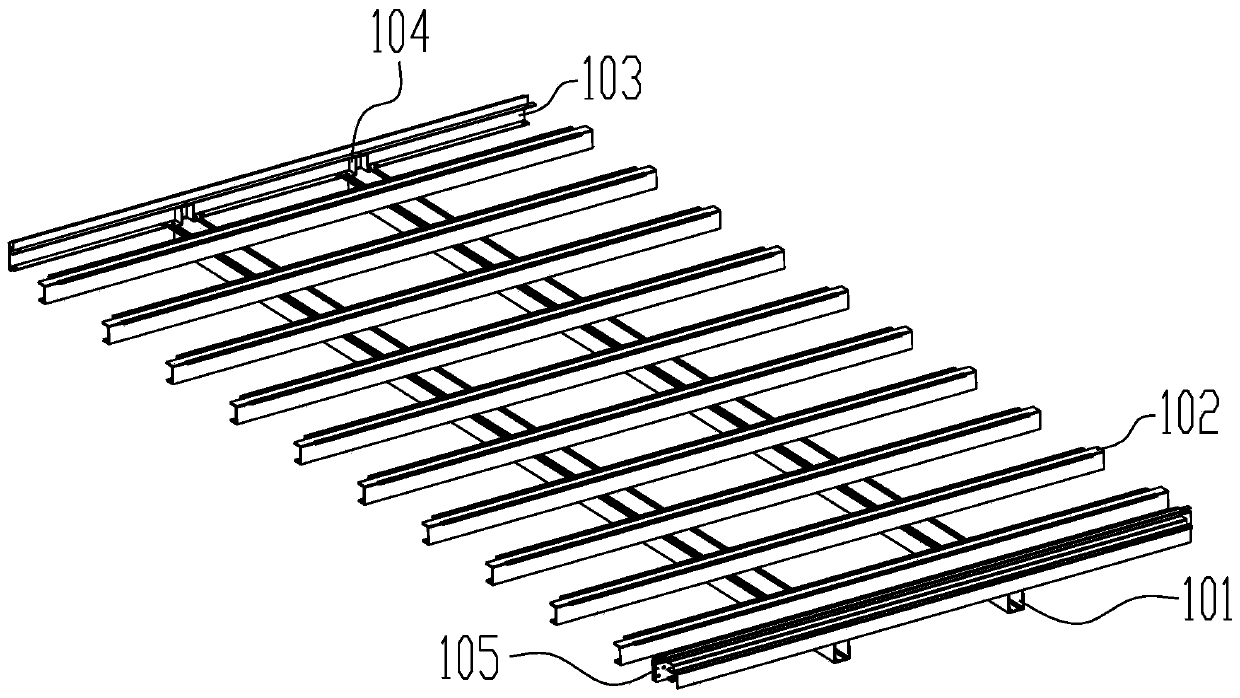
[0028] Such as figure 1 , figure 2 , image 3 , Figure 4 , Figure 5 , Image 6 , Figure 7 As shown, the present embodiment is an all-aluminum alloy van type truck and its manufacturing process, including a bottom plate assembly 1, a top plate assembly 2, a left side plate assembly 3, a right side plate assembly 4, and a rear door assembly 5. Front side panel assembly 6. The bottom plate assembly 1 is fixed to the truck chassis frame by two U-shaped bolts. Two of the straight beams 101 just fall on the frame frame. On the two straight beams 101, 10 cross beams 102 are arranged in a 90° direction. The connection with the straight beam 101 is bolted. The front end of the straight beam 101 supports the front side beam 103 through two front support members 104 as transitional connections, and the upper and lower surfaces are respectively connected with the front side beam 103 and the straight beam 101 by bolts. The rear end of the straight beam 101 is bolted and fixed with the rear side beam 105; the roof assembly 2 is located on the top of the carriage and the rear upper beam 201 and the front upper beam 202 are divided into this assembly. The roof falls on the top of the carriage frame and is fixed by riveting , The space between the folded edge of the top plate 201 and the frame profile is completely filled with sealant for sealing. The two ends of the top plate reinforcement 202 are respectively framed on the side of the left upper beam 302 and the right upper beam 402 and then passed through rivets. Riveted and fixed; the left side plate assembly 3 is a quadrilateral frame structure composed of the left side beam 301, the left upper beam 302, the front column (left) 303, and the rear column (left) 304. Side closed unit plate, the left closed unit plate relies on the stainless steel connectors on the four corners as transition connections to connect with other plate units, where one end of the cross beam 102 in the bottom plate assembly 1 is a U-shaped clip into the lower side of the left beam 301 The structure of the right side panel assembly 4 is the same as that of the left side panel assembly 3, except that it is symmetrical to the left side panel assembly 3 during installation; the rear door assembly 5 is composed of the rear left door panel 501 and the rear right panel. The door panel 502 and the backing door panel group frame are composed together. The rear left door panel 501 and the rear right door panel 502 are connected to the backing group frame by riveting. At the same time, the surface of the backing group frame and the door panel is coated with structural adhesive. In order to further improve the structural reliability of the group frame, the backing group frame is a frame structure formed by combining a variety of aluminum profiles, and each profile is combined by welding. The front side panel assembly 6 is embedded in a quadrilateral frame composed of the front side beam 104, the front upper beam 203, the front pillar (left) 303, and the front pillar (right) 404. Because its external frame is shared with other assemblies, Divided into other assemblies, the front side panel assembly 6 is composed of the front side panel skin 605, the front decorative strip 606 and the surrounding profile combination frame. The front decorative strip 606 and the front side panel skin 605 are riveted and the profile group Welding between the boxes.
[0029] Such as figure 2 , Picture 11 As shown, the bottom plate assembly 1 of this embodiment includes a straight beam 101, a cross beam 102, a front side beam 103, a front support 104, and a rear side beam 105; the straight beam 101 is a closed extruded aluminum profile, and both sides of the profile section are designed with edge With the groove in the length direction, the bolt head can be clamped into the groove from both ends of the straight beam 101 and move along the length direction; the cross beam 102 is an open aluminum profile with a cross-section similar to the C-shape, which is placed in the straight beam 101 in a 90° direction On the upper surface, the lower surface of the beam 102 is machined with bolt holes to be connected to the straight beam 101 by bolts. The two ends of the beam 102 are punched with notches to be inserted into the left beam 301 and the right beam 401; the front beam 103 is an open aluminum alloy profile and the upper side of the profile is designed It has a U-shaped slot structure. The upper surface and left and both sides of the front side beam 103 are processed with bolt holes, and the lower surface is processed into avoidance gaps; the front support 104 is made of aluminum alloy veneer through bending. "Single-shaped structure". Bolt holes are machined up and down to connect with the front side beam 103 and the straight beam 101 respectively to support the transition; the rear side beam 105 is a closed extruded aluminum profile placed on the straight beam 101, and the lower surface is processed A bolt hole is fixed to the straight beam 101 by bolts, the rear side beam 105 is processed with notches at both ends and a pair of perforations are processed through bolts to fix the rear side beam 105 with the rear column (left) 304 and the rear column (right) 403; the entire bottom plate assembly The top of 1 is laid with a 5052 series pointer pattern aluminum veneer, and the whole board is placed on the bottom support structure formed by the straight beam 100 and the cross beam 102 and fixed by riveting.
[0030] Such as image 3 , Figure 8 , Picture 10 As shown, the top plate assembly 2 of this embodiment includes a rear upper beam 201, a top plate reinforcement 202, a front upper beam 203, and a top plate 204; the rear upper beam 201 is a closed extruded aluminum profile and has bolt holes at both ends. It is connected with the upper rear connector (left) 314 and the upper rear connector (right) 413 respectively. The two ends of the rear upper beam 201 are also cut with 45° profile splicing angles to ensure that they are connected to the rear pillar (left) 304 and rear Column (right) 403 is spliced; the top plate reinforcement 202 is an open profile with a cross-section similar to a "ji" shape, and glue grooves are designed on both sides for glueing and bonding with the top plate 204. The top plate reinforcement 202 is riveted on the left upper beam 302 and the right upper beam 402 upper; the front upper beam 203 is a closed extruded aluminum alloy profile and the lower surface is designed as a U-shaped groove structure. Both ends of the profile are processed with three round holes through bolts or structural rivets and the front upper connector (left) 312, front The upper connector (right) 414 is connected; the top plate 204 is made of 1.0mm thick 5052 series aluminum alloy veneer, which covers the top of the carriage by bending. The last edge around the top plate is bent at 45° for easy operation Glue sealing treatment.
[0031] Such as Figure 4 , Figure 8 , Picture 9 , Picture 10 , Picture 11 As shown, the left side panel assembly 3 of this embodiment includes a left beam 301, a left upper beam 302, a front pillar (left) 303, a rear pillar (left) 304, a left panel 305, a left decorative strip 306, and a left panel. Group frame (bottom) 307, left board leather group frame (up) 308, left board leather group frame (front) 309, left board leather group frame (rear) 310, front lower connector (left) 311, front upper connector (Left) 312, lower rear connecting piece (left) 313, upper rear connecting piece (left) 314, left side plate reinforcing rib 315; left beam 301 is made of aluminum alloy profile and the section structure of the profile is the same as that of the front beam 103, both ends of the profile Each processing has two round holes located on the upper and lower surfaces, respectively. The upper surface of the profile is designed with a U-shaped slot structure to clamp the left side sealing plate assembly, and the lower surface is designed to be inserted into the beam 102; The beam 302 is a closed aluminum alloy profile with three round holes on each end; the front pillar (left) 303 is a closed aluminum profile, and the upper and lower ends are processed to avoid the gap in order to ensure that the profile splicing does not interfere, and to ensure the connection. There are round holes; the rear column (left) 304 is a closed aluminum profile, the upper end is processed with profile splicing avoidance gaps and round holes for connection, and the lower end is processed with two round holes; the left side plate 305 is made of aluminum with a thickness of 1.5mm The alloy veneer is the raw material. On the left side of the slab 305, rectangular grooves with uniform spacing are pressed parallel to the short side direction. The grooves are embedded with a reinforcing left decorative strip 306 and the left decorative strip 306 is connected to the left Waterproof glue is applied between the side panels 305 and then riveted to fix; the left decorative strip 306 is a square tube aluminum profile embedded in the pressure groove of the left panel 305; the left panel skin group frame (bottom) 307 is cut at both ends by 45° Angled aluminum profile, the profile section is similar to U-shaped structure; the left panel skin group frame (top) 308 has the same structure and length as the left panel skin group frame (bottom) 307; the left panel skin group frame (front) 309 profile section and The structure is the same as the left panel frame (top) 308, and the length is different; the left panel frame (rear) 310 has the same structure and length as the left panel frame (front) 309; the front and bottom connector (left) 311 It is made of stainless steel plate for bending and welding to connect the frame section of the carriage. Two round holes are machined on the upper and lower surfaces, and four round holes are machined on the side. The front lower connector (left) 311 connects the front side beam 103. The left beam 301 and the front column (left) 303 are connected together by bolts or structural rivets; the front upper connecting piece (left) 312 is a welded joint made of stainless steel plate after sheet metal processing, with bolts processed on the connecting piece The holes are used to connect with bolts. The upper front connector (left) 312 connects the front pillar (left) 303, the upper front beam 203, and the upper left beam 302 together by bolts or structural rivets; the lower rear connector (left) 313 is The stainless steel plate is used for bending and welding. The surface of the connector is processed with bolt holes. The rear lower connector (left) 313 connects the rear side beam 201, the rear column (left) 304, and the left beam 301 through bolts or structural rivets. Together; rear upper connector (left) 3 14 is the use of stainless steel plate for punching, bending and forming, the connecting piece is processed with bolt holes for connection, the rear upper connecting piece (left) 314 connects the rear pillar (left) 304, the rear upper beam 201, and the left upper beam 302 To one; the side plate reinforcement 315 is an aluminum profile with a "several" shape in cross section, which is fixed to the left side panel 305 by riveting to strengthen the entire left side panel.
[0032] Such as Figure 4 , Figure 8 , Picture 9 , Picture 10 , Picture 11 As shown, the overall component composition, material, and assembly process of the right side panel assembly 4 of this embodiment are the same as those of the left side panel assembly 3, and the two are located on the left and right sides of the car in a symmetrical manner. The implementation mode will not be repeated here.
[0033] Such as Image 6 As shown, the rear door assembly 5 of this embodiment includes a rear left door panel 501, a rear right door panel 502, a rear left door panel group frame (upper) 503, a rear left door panel group frame (lower) 504, and a rear left door panel group frame (left) 505, rear left door panel group frame (right) 506, rear right door panel group frame (up) 507, rear right door panel group frame (down) 508, rear right door panel group frame (left) 509, rear right door panel group frame (right) 510; The rear left door panel 501 is a rectangular flat plate made of 5052 series aluminum veneers with a thickness of 2.0mm by bending and welding. The rear left door panel 501 has countersunk rivet holes on the folded edge. The rear left door panel 501 is fixed to the door panel by rivets The structure and size of the rear right door panel 502 are the same as those of the rear left door panel 501; the rear left door panel group frame (upper) 503 is an aluminum profile and one end is cut with a 45° splicing angle. The lower surface of the profile is designed with a small groove for Glue the profile and the door panel together. At the same time, the side of the profile and the door panel are folded and then riveted with rivets. Argon arc welding is performed between the profile group frames; the rear left door panel group frame (below) 504 profile section and rear The left door panel frame (top) 503 is the same, and the same end is cut with a 45° profile splicing angle; the rear left door panel frame (left) 505 is an aluminum profile, and the bottom surface is designed with a glue groove. Both ends are cut with a 45° profile splicing angle ; Rear left door panel group frame (right) 506 is made of aluminum profile, which is connected to the profile group frame by welding; rear right door panel group frame (top) 507 has the same structure and size as rear left door panel group frame (bottom) 504; rear right door panel group The frame (bottom) 508 has the same structure and dimensions as the rear left door panel group frame (top) 503; the rear right door panel group frame (left) 509 is made of aluminum profiles, and the section of the profile is designed according to the sealing requirements between the rear doors. The structure and size of the rear right door panel group frame (right) 510 are the same as the rear left door panel group frame (left) 505.
[0034] Such as Figure 7 As shown, the front side panel assembly 6 of this embodiment includes a front panel skin group frame (upper) 601, a front panel skin group frame (lower) 602, a front panel skin group frame (left) 603, and a front panel skin group frame ( (Right) 604, front panel skin 605, front decorative strip 606; front panel skin group frame (top) 601 is a U-shaped aluminum alloy profile with a 45° splicing angle cut at both ends of the profile; front panel skin group Frame (bottom) 602, front skin group frame (left) 603, and front skin group frame (right) 604 are identical in structure to front skin group frame (up) 601, except for the different assembly positions; front skin 605 is Using 1.5mm thick 5052H24 series aluminum alloy veneer as raw material, the board surface is parallel to the short side with grooves, and aluminum alloy decorative strips are embedded in the grooves to strengthen the surface; the front decorative strip 606 is a square tube in section The aluminum profile is embedded in the pressure groove of the front plate skin 605 by riveting.
[0035] In the actual production process, each sub-assembly is individually assembled into a single unit plate, and then each sub-assembly unit is assembled into a car body on the final assembly line; for example, the bottom plate assembly 1 first distributes the crossbeam 102 in two at a specified interval. Then fasten the bolts to the straight beam 101, place the rear side beam 105 on the tail end of the straight beam 101, determine the position and then tighten the bolts, and finally place the front support 104 on the head end of the two straight beams 101 and use Fasten the bolts and then install the front side beam 103 to the front support 104, and finally lay the bottom plate to complete the assembly work of the entire bottom plate assembly 1. The top plate assembly 2 is on the assembly line to wait for the other plate units to be hoisted on the rear beam After 201 and the front upper beam 203 are fixed to the carriage frame, the top plate reinforcement 202 is placed between the left upper beam 302 and the right upper beam 402 and riveted with rivets. Finally, the bottom plate cover is riveted and glued to the top of the carriage to complete the assembly; In assembly 3, the left side plate 305 is grooved, and then sealant is applied in each groove, and the left decorative strip 306 is inserted into the groove and connected by riveting, and then the U-shaped profile around the left side plate 305 The welding frame is finally clamped into the large rectangular frame composed of the left beam (301), the left upper beam 302, the front column (left) 303, and the rear column (left) 304, and the four corners are connected by stainless steel connectors; The assembly process route of the right side panel assembly 4 is the same as that of the left panel assembly 3; the rear door assembly 5 is first assembled by welding the backing frame profile, and then the rear left door panel 501 and the rear right door panel 502 are covered on the backing frame Riveting with rivets; the front side panel assembly 6 first performs groove processing on the front side panel skin 605, and then seals the front decorative strip 606 into the groove to be riveted and fixed in each groove, and then fix the surrounding frame Combine and weld. When assembling the whole vehicle assembly line, the bottom plate assembly 1 is used as the basis, and then the left side plate assembly 2 is hoisted, and then the front side plate assembly 6 is clamped into the groove formed by the profile combination and the right side plate assembly 4 is hoisted, then before assembly The upper beam 203, the rear upper beam 201 and the top plate reinforcement 202 are then hinged to install the rear door assembly 5 on the column, and finally the top plate 204 is riveted and sealed with glue on the periphery.
[0036] The above description only expresses the preferred embodiments of the present invention, and the description is more specific and detailed, but it should not be understood as a limitation to the patent scope of the present invention. It should be pointed out that for those of ordinary skill in the art, without departing from the concept of the present invention, several modifications, improvements and substitutions can be made, and these all fall within the protection scope of the present invention. Therefore, the protection scope of the patent of the present invention should be subject to the appended claims.

PUM

no PUM

Description & Claims & Application Information

We can also present the details of the Description, Claims and Application information to help users get a comprehensive understanding of the technical details of the patent, such as background art, summary of invention, brief description of drawings, description of embodiments, and other original content. On the other hand, users can also determine the specific scope of protection of the technology through the list of claims; as well as understand the changes in the life cycle of the technology with the presentation of the patent timeline. Login to view more.

Similar technology patents

Classification and recommendation of technical efficacy words

  • Reduce the weight of the carriage
  • Improves strength and stability

Truck carriage

Owner:重庆勇图机械工业有限公司

Travel trailer

PendingCN110588493ASave compartment spaceReduce the weight of the carriagePhotovoltaic supportsVehicle with living accommodationElectricityCells panel
Owner:BEIJING ANGEL IMPRINT HEALTH MANAGEMENT CO LTD

In-situ heat regeneration remixing and paving technology of asphalt pavement

ActiveCN103590296ASolve the poor connection between layersImproves strength and stabilityIn situ pavingsRoads maintainenceHeat regenerationPitch blende
Owner:CCCC SHEC DONGMENG ENG CO LTD

Auxiliary frame of wheel loader

Owner:SHAANXI SHENGMAI PETROLEUM
Why Eureka
Try Eureka