
Same-direction flow flotation separation assembly

A technology of separating components and co-current flow, which is applied in the directions of flotation water/sewage treatment, water/sewage treatment, flocculation/sedimentation water/sewage treatment, etc. Certain isolation and other issues can be achieved to achieve the effect of efficient separation and laminar flow

Pending Publication Date: 2019-12-20
WUXI HI TECH ENVIRONMENTAL PROTECTION EQUIP TECH
View PDF1 Cites 0 Cited by
  • Summary
  • Abstract
  • Description
  • Claims
  • Application Information

AI Technical Summary

Problems solved by technology

At present, the common air flotation tanks with sloping plate components have a single sloping plate, and there is no certain isolation between sludge and clean water, which makes it easy for sludge to enter the clean water chamber with the water flow, thereby reducing the flow rate of the effluent. quality

Method used


Image

  • Same-direction flow flotation separation assembly
  • Same-direction flow flotation separation assembly
  • Same-direction flow flotation separation assembly

Examples


Embodiment Construction

[0032] The specific implementation manners of the present invention will be further described in detail below in conjunction with the accompanying drawings and embodiments. The following examples are used to illustrate the present invention, but are not intended to limit the scope of the present invention.

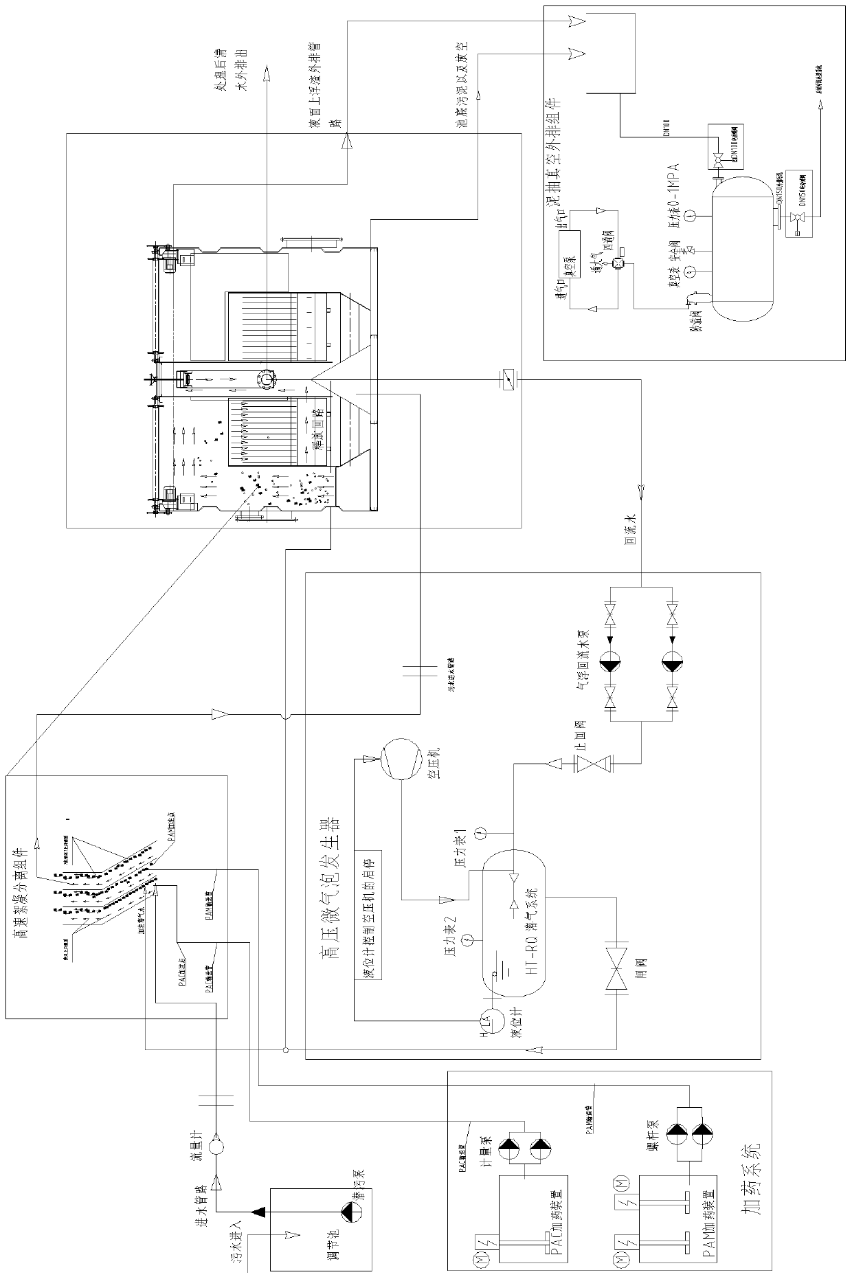
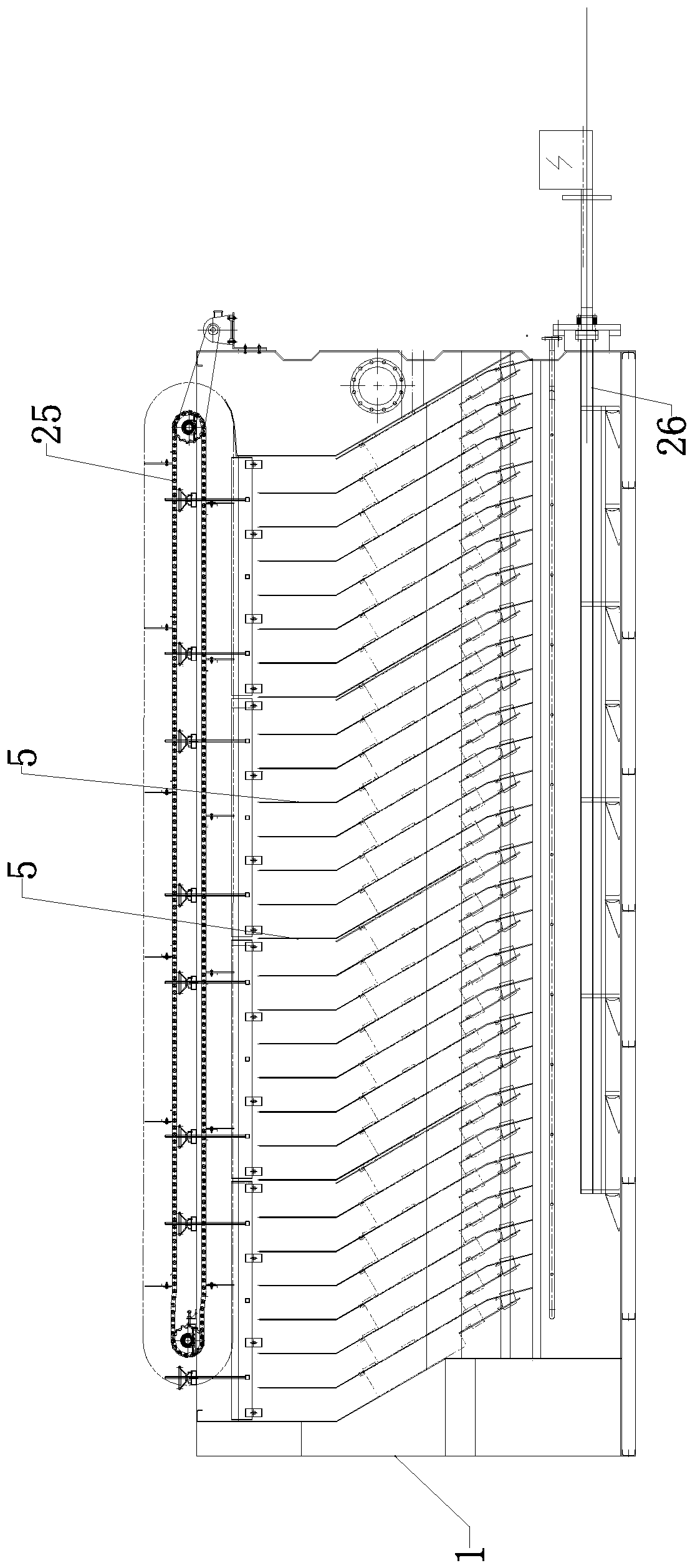
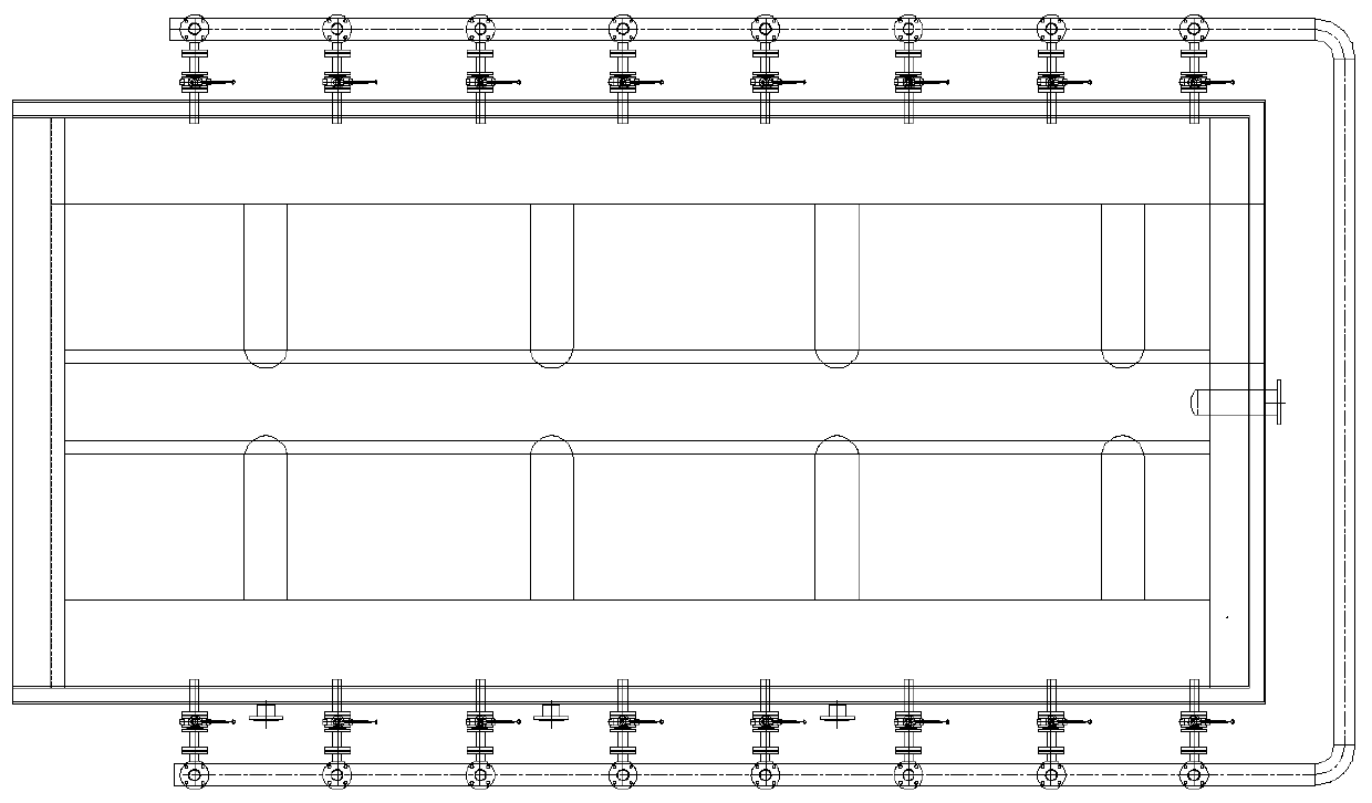
[0033] see Figure 1 to Figure 18 , a solid-liquid separation tank for co-current flow flotation, comprising a tank body 1, in which a contact chamber 2, a separation chamber 3 and a clean water collection chamber 4 connected to each other are arranged in sequence along the flow direction of the water flow, and a co-flow flow chamber is arranged in the separation chamber. The flotation separation assembly 4, the cocurrent flow flotation separation assembly includes a plurality of inclined plate assemblies 5, the inclined plate assembly includes a vertically arranged straight plate 6, a collection swash plate 7 whose top is connected to the bottom of the straight plate, and...


PUM


Abstract

The invention relates to a same-direction flow flotation separation assembly which comprises a plurality of inclined plate assemblies, wherein the inclined plate assemblies comprise vertically-arranged straight plates, trapping inclined plates of which the top ends are connected to the bottom ends of the straight plates, and mud sliding inclined plates of which the top ends are connected to the bottom ends of the trapping inclined plates; sludge partition plates are arranged at the bottoms of the inclined plate assemblies and located between the adjacent inclined plate assemblies; the space between each sludge partition plate and the inclined plate assembly on the front side of the sludge partition plate is a clear water conveying cavity; and the space between each sludge partition plate and the inclined plate assembly on the rear side of the sludge partition plate is a sludge conveying cavity. The same-direction flow flotation separation assembly can prevent sludge from entering a clear water collection chamber.

Description

technical field [0001] The invention relates to a flocculation separation device for an air flotation tank, in particular to a cocurrent flow flotation separation component. Background technique [0002] The air flotation tank is a kind of sewage treatment equipment, which includes a contact chamber, a separation chamber and a clean water collection chamber, and the separation chamber is equipped with a sloping plate assembly. At present, the common air flotation tanks with sloping plate components have a single sloping plate, and there is no certain isolation between sludge and clean water, which makes it easy for sludge to enter the clean water chamber with the water flow, thereby reducing the flow rate of the effluent. quality. [0003] In view of the above-mentioned defects, the designer is actively researching and innovating in order to create a new structure of co-flow flotation separation components, so that it has more industrial use value. Contents of the inventi...

Claims


Application Information

Patent Timeline
Patent Type & Authority Applications(China)
IPC IPC(8): C02F1/24C02F1/52
CPCC02F1/24C02F1/5281C02F2201/002
Inventor 戴文强赵洪启
Owner WUXI HI TECH ENVIRONMENTAL PROTECTION EQUIP TECH
Learn More