Water turbine rotating wheel main shaft flange with corrosion-resistance friction structure

A shaft flange and water turbine technology, which is applied in couplings, hydroelectric power generation, mechanical equipment, etc., can solve the high stability requirements of the joint surface of the water turbine runner and the main shaft, which affects the stability of the joint surface of the water turbine runner and the main shaft, Erosion affects stability, reliability, service life and other issues, and achieves the effect of reducing the possibility of water flow entering the flange sealing sleeve, increasing connection stability, and simple structure

Pending Publication Date: 2019-12-20
浙江亚泰连接盘制造有限公司
View PDF0 Cites 0 Cited by
  • Summary
  • Abstract
  • Description
  • Claims
  • Application Information

AI Technical Summary

Problems solved by technology

In the prior art, the runner of the water turbine is connected to the main shaft of the generator through a flange. Since the water head of the high-head water turbine is relatively high, the impact of the water flow is strong, and the speed of the runner is relatively high. Therefore, the stability of the interface between the runner and the main shaft of the water turbine more demanding
In addition, the joint surface between the turbine runner and the main shaft flange is just at the main part of the impact of the strong impact water flow, and the erosion of the joint surface by the water flow seriously affects its stability, reliability and service life
Obviously, there is a strong impact force in the joint surface structure between the turbine runner and the main shaft flange in the prior art. The water flow affects the stability of the joint surface between the turbine runner and the main shaft, and the erosion of the water flow on the joint surface affects its stability, reliability and use. Therefore, it is necessary to propose a hydraulic turbine runner main shaft flange with an anti-corrosion friction structure

Method used


Image

  • Water turbine rotating wheel main shaft flange with corrosion-resistance friction structure
  • Water turbine rotating wheel main shaft flange with corrosion-resistance friction structure

Examples


Embodiment Construction

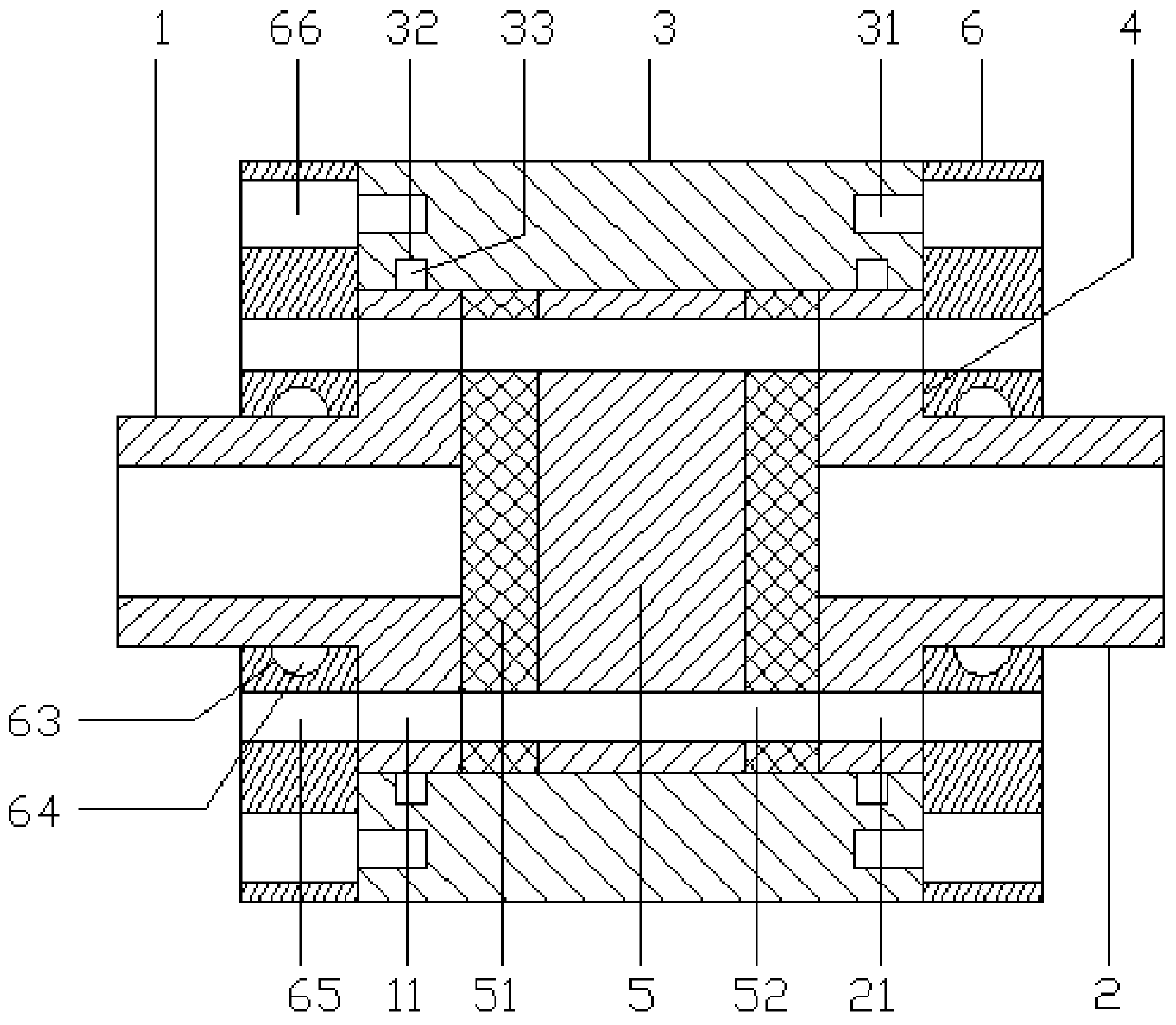
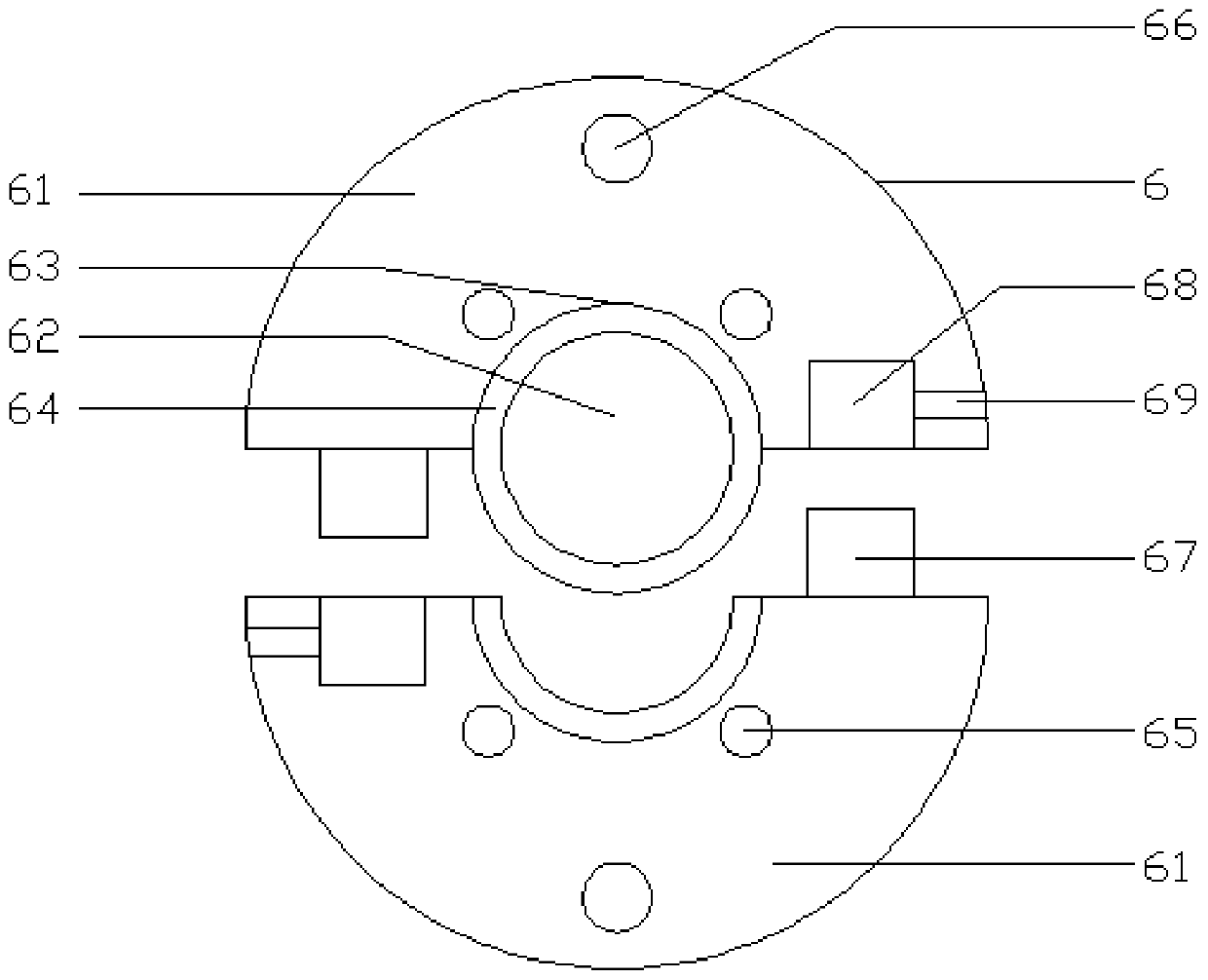
[0017] Referring to the accompanying drawings, the invention shows a water turbine runner main shaft flange with anti-corrosion friction structure, including main shaft flange 1, shaft flange 2, flange sealing sleeve 3, flange installation groove 4, anti-corrosion friction module 5 and flange A sheet fastening mechanism 6, a shaft flange 2 is provided on the right side of the main shaft flange 1, a flange sealing sleeve 3 is provided between the main shaft flange 1 and the shaft flange 2, and the flange sealing sleeve 3 There is a flange installation groove 4 inside, the flange connection piece of the main shaft flange 1 and the shaft flange 2 is located inside the flange installation groove 4, the flange connection piece of the main shaft flange 1 and the rotation shaft flange 2 An anti-corrosion friction module 5 is arranged between the main shaft flange 1 and the rotating shaft flange 2. A flange fastening mechanism 6 is provided on the outside of the main shaft flange 1 and...


PUM


Abstract

The invention discloses a water turbine rotating wheel main shaft flange with a corrosion-resistance friction structure. The water turbine rotating wheel main shaft flange comprises a main shaft flange, a rotating shaft flange, a flange sealing sleeve, a flange mounting groove, a corrosion-resistance friction module and a flange plate fastening mechanism. Compared with the prior art, the water turbine rotating wheel main shaft flange is reasonable in design and simple in structure; through a mode of arranging the flange sealing sleeve and the corrosion-resistance friction module, a first sealing ring and a second sealing ring are matched to firmly seal contacted surfaces of the main shaft flange and the rotating shaft flange; through a corrosion-resistance friction coating layer arranged on the corrosion-resistance friction module, the friction force of the contacted surfaces of the main shaft flange and the rotating shaft flange can be increased, and the corrosion resisting function is achieved; and water currents can be isolated from the contacted surfaces of the main shaft flange and the rotating shaft flange by the flange sealing sleeve, so that the flange connecting stability,reliability and durability are improved, and the popularization is facilitated.

Description

【Technical field】 [0001] The invention relates to the technical field of fasteners, in particular to a water turbine runner main shaft flange with an anti-corrosion friction structure. 【Background technique】 [0002] Pelton turbines are often called high head turbines because of their high water heads. In normal operation, the water flow with high head and high pressure impacts the runner of the turbine and drives the main shaft of the turbine and the main shaft of the generator to rotate, thereby driving the rotor of the generator to cut the magnetic lines of force to generate electricity. In the prior art, the runner of the water turbine is connected to the main shaft of the generator through a flange. Since the water head of the high-head water turbine is relatively high, the impact of the water flow is strong, and the speed of the runner is relatively high. Therefore, the stability of the interface between the runner and the main shaft of the water turbine Higher requir...

Claims


Application Information

Patent Timeline
Patent Type & Authority Applications(China)
IPC IPC(8): F16D1/033F16J15/06F03B1/00
CPCF03B1/00F16D1/033F16D2300/08F16J15/06Y02E10/20
Inventor 陆建生
Owner 浙江亚泰连接盘制造有限公司
Why Eureka
Try Eureka