A Compensation Method for Low Frequency Energy of Seismic Signals

A low-frequency energy and seismic signal technology, applied in seismic signal processing and other directions, can solve problems such as inappropriate seismic signal acquisition methods, and achieve the effect of good algorithm stability

Active Publication Date: 2021-03-30
CHINA PETROLEUM & CHEM CORP +1
View PDF2 Cites 0 Cited by
  • Summary
  • Abstract
  • Description
  • Claims
  • Application Information

AI Technical Summary

Problems solved by technology

This technology is mainly used in vibroseis data acquisition, and is not applicable to general seismic signal acquisition methods

Method used


Image

  • A Compensation Method for Low Frequency Energy of Seismic Signals
  • A Compensation Method for Low Frequency Energy of Seismic Signals
  • A Compensation Method for Low Frequency Energy of Seismic Signals

Examples


Embodiment 1

[0108] Pulse test analysis

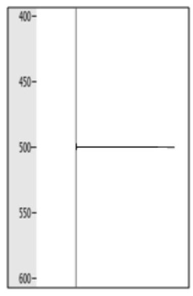
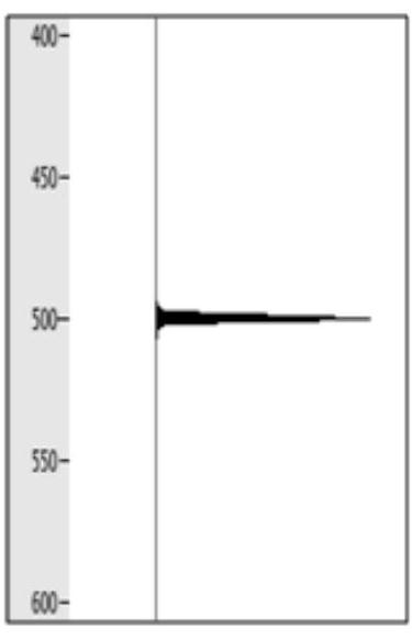
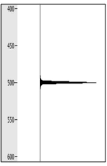
[0109] Pulse testing is the most basic method to verify the correctness of mathematical algorithms. Adopt the above-mentioned low-frequency energy compensation method of the present invention to analyze the pulse test result, Fig. 1 (a) is the pulse spectrum that does not carry out low-frequency energy compensation of test, Fig. 1 (b), Fig. 1 (c), Fig. 1 (d), Figure 1(e) is the compensation result diagram of different operators respectively, figure 2 Pulse amplitude spectra under different compensation parameters in Example 1 of the present invention.

[0110] By applying this method, the compensated spectrum ( figure 2 ) The low-frequency energy (especially below 20Hz) is significantly enhanced, and the corresponding symbols on the spectrogram are (b) (c) (d) (e), and the low-frequency energy is gradually enhanced.

Embodiment 2

[0112] Synthetic record test analysis

[0113] Figure 3(a) is the designed synthetic record. The energy of different frequencies is basically uniform. Operators with different parameters are used to compensate the low frequency of the synthetic record. The results are shown in Figure 3(b)(c)(d)(e). Figure 4 For the corresponding amplitude spectrum, the comparison shows that this method retains the relative change law of the designed reflection coefficient, compensates the low-frequency components, and highlights the energy reflected by the interface.

[0114] By applying this method, the low-frequency energy of the compensated spectrum ( Figure 4 ) (especially below 20Hz) is significantly enhanced, and the corresponding symbols on the spectrogram are (b) (c) (d) (e), and the low-frequency energy is gradually enhanced.

Embodiment 3

[0116] Raw Single Shot Record Test

[0117] During the acquisition process of seismic exploration, because the frequency range received by the geophone and the instrument is not all-pass, it is often to avoid surface waves and strong low-frequency interference, and to prevent record overshooting. Limitations are designed at the low-frequency end, generally due to the lack of low-frequency energy . The low-frequency component of the seismic reflection wave has a strong penetrating ability, which is more conducive to imaging the surface of the buried hill and the inside of the buried hill.

[0118] Figure 5(a) is the original single-shot record, and Figure 5(b)(c)(d)(e) is the result of low-frequency compensation of the data with different parameters. With the enrichment of low-frequency components, the energy of mid-to-deep reflection waves gradually increases, and the reflection characteristics of the buried hill surface and the underlying strata are clear. Image 6 is the a...


PUM


Abstract

The invention relates to a seismic signal low-frequency energy compensation method. The seismic signal low-frequency energy compensation method includes the following steps: (1) amplitude informationin seismic data excited by a seismic focus is received; (2) the amplitude information obtained in the step (1) is subjected to Fourier transformation to obtain an amplitude frequency spectrum; (3) onthe basis of the spectrum characteristic of the amplitude frequency spectrum, a compensation operator is determined; and (4) convolution processing is conducted on the amplitude frequency spectrum inthe step (2) through the compensation operator, and thus seismic data after low-frequency energy compensation are obtained. The invention further relates to a device utilizing the seismic signal low-frequency energy compensation method. The low-frequency information in seismic signals can be compensated well, algorithm stability is good, the signals at other frequency bands are effectively protected while the low-frequency effective signals are compensated, and meanwhile, the natural characteristics of the high-frequency signals and the low-frequency signals are maintained well while compensation.

Description

technical field [0001] The invention relates to the technical field of seismic data processing, in particular to a compensation method for low-frequency energy of seismic signals. Background technique [0002] Low-frequency signals are more capable of penetrating formation than high-frequency signals, and one of the greatest potentialities of using low-frequency components is to improve the velocity model, which will help high-frequency imaging. First, recognizable prestack signals are required for subsalt velocity analysis. Prestack data are usually of poorer quality than stacked data. Improving the quality of low-frequency signals will help velocity analysis. Secondly, the low frequency helps to identify the bottom of the salt body in areas with poor data quality, and is conducive to better picking in areas with good data quality. Third, some of the more potential wave equation inversion algorithms require stable low frequencies. The seismic data obtained after low-frequ...

Claims


Application Information

Patent Timeline
Patent Type & Authority Patents(China)
IPC IPC(8): G01V1/36
CPCG01V1/36
Inventor 薛永安刘秉龙陈习峰
Owner CHINA PETROLEUM & CHEM CORP
Why Eureka
Try Eureka