Migration and erasure code-based reconstruction coupled rapid prediction repair method and implementation

A repair method and erasure code technology, applied in the field of fast predictive repair, can solve problems such as the inability to achieve fast data repair, and achieve the effect of ensuring reliable data storage and fast data repair

Active Publication Date: 2019-12-20
云链网科技(广东)有限公司
View PDF6 Cites 8 Cited by
  • Summary
  • Abstract
  • Description
  • Claims
  • Application Information

AI Technical Summary

Problems solved by technology

[0009] It can be seen that neither of the above two technical point...

Method used


Image

  • Migration and erasure code-based reconstruction coupled rapid prediction repair method and implementation
  • Migration and erasure code-based reconstruction coupled rapid prediction repair method and implementation
  • Migration and erasure code-based reconstruction coupled rapid prediction repair method and implementation

Examples


Embodiment 1

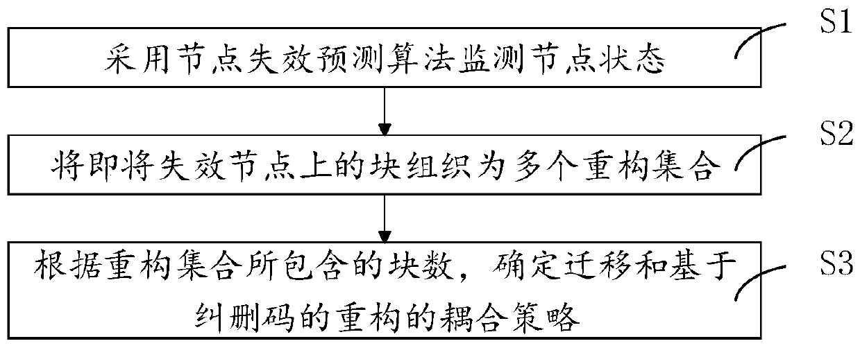
[0056] like figure 1 As shown, a fast predictive repair method coupled with migration and reconstruction based on erasure codes, including:

[0057] S1. Use node failure prediction algorithm to monitor node status;

[0058] S2. Organize the blocks on the node about to fail into multiple reconstruction sets;

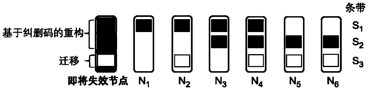
[0059] S3. According to the number of blocks included in the reconstruction set, determine a coupling strategy for migration and erasure code-based reconstruction.

[0060] The reconstruction method based on erasure code needs to read k blocks from other k healthy nodes when repairing a block. In actual storage system deployment, in order to reduce the network overhead required for repair, the value of k is generally selected to be small (for example, in the Facebook F4 storage system, the value of k is 10).

[0061] Existing large-scale storage systems are usually built on hundreds or even thousands of storage servers (referred to as "nodes"). Therefore, in this embod...

Embodiment 2

[0064] On the basis of Embodiment 1 of the present invention, the use of node failure prediction algorithm to monitor node status includes:

[0065] Step 1.1. Monitor and collect the attribute values ​​returned by the SMART module;

[0066] Step 1.2. Input the relevant attribute values, and use the node failure prediction algorithm to calculate the node failure probability. If the node failure probability exceeds a given threshold, it is judged that the node is about to fail.

Embodiment 3

[0068] On the basis of Embodiment 1 of the present invention or Embodiment 2 of the present invention, the organization of the blocks on the about-to-be-failure node into multiple reconstruction sets includes:

[0069] Obtain the metadata information of the system, mainly including the storage node ID of all blocks in each stripe, and the logical block number of each block in the stripe to which it belongs. The logical block number is used to determine the reconstruction time based on the erasure code. Decoding parameters to be used;

[0070] Determine all repaired blocks stored on the node about to fail and the stripes they belong to;

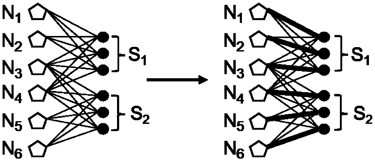
[0071] Organize the repaired block into a plurality of reconstruction sets, and determine the ID of the healthy node selected to read data when each repaired block is reconstructed by using the erasure code.

[0072] In a specific embodiment, the specific steps of organizing the blocks on the node about to fail into multiple reconstruction se...


PUM


Abstract

The invention discloses a migration and erasure code-based reconstruction coupled rapid prediction repair method. The method comprises the steps of monitoring a node state by adopting a node failure prediction algorithm; organizing the blocks on the nodes about to fail into a plurality of reconstruction sets; and determining a coupling strategy of the migration and erasure code-based reconstruction according to the number of blocks contained in the reconstruction sets. According to the teaching of the above embodiment, the migration and erasure code-based reconstruction coupled rapid prediction repair can be realized by combining the failure prediction, thereby not only accelerating the data restoration, but also reducing the I/O operation needed by the repair compared with the reconstruction based on the erasure codes. The invention further discloses a migration and erasure code-based reconstruction coupled rapid prediction repair device.

Description

technical field [0001] The invention relates to the field of storage system data fault tolerance, in particular to a fast predictive repair method and device coupled with migration and reconstruction based on erasure codes. Background technique [0002] In the field of storage system data fault tolerance, the existing technologies are mainly active repair based on failure prediction and passive repair based on erasure code. The relevant technical characteristics and defects thereof will be introduced in sequence below. [0003] 1) Proactive repair based on failure prediction. [0004] Proactive repair needs to accurately identify which devices are about to fail, and perform data repair operations before the device fails, so as to ensure data reliability. Existing commercial storage devices have built-in self-monitoring analysis and early warning firmware (that is, SMART, the English full name is Self-Monitoring, Analysis and Reporting Technology), which can monitor and rep...

Claims


Application Information

Patent Timeline
IPC IPC(8): G06F11/10
CPCG06F11/1004
Inventor 沈志荣李柏晴
Owner 云链网科技(广东)有限公司
Why Eureka
Try Eureka