Radioactive source positioning reconstruction method based on multi-energy system response matrix

A system response and radioactive source technology, applied in the field of radioactive source positioning and reconstruction based on the multi-energy system response matrix, can solve the problem of different gamma ray penetration ability and detector response, and achieve the effect of strong portability

Active Publication Date: 2019-12-20
SICHUAN UNIVERSITY OF SCIENCE AND ENGINEERING +1
View PDF8 Cites 6 Cited by
  • Summary
  • Abstract
  • Description
  • Claims
  • Application Information

AI Technical Summary

Problems solved by technology

[0004] However, unlike the field of nuclear medicine, the number, type and location distribution of radioactive sources are often unknown in the fields of decommissioning of nuclear facilities, nuclear safety and nuclear security, and the penetration ability of gamma rays with different energies to the coding plate and the The detectors respond differently

Method used


Image

  • Radioactive source positioning reconstruction method based on multi-energy system response matrix
  • Radioactive source positioning reconstruction method based on multi-energy system response matrix
  • Radioactive source positioning reconstruction method based on multi-energy system response matrix

Examples


Embodiment 1

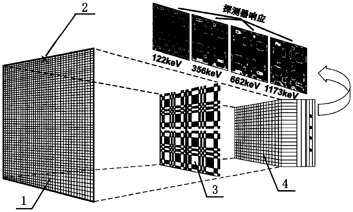
[0054] Embodiment 1: see Figure 1 to Figure 4 , a radioactive source location and reconstruction method based on a multi-energy system response matrix, using a coded aperture imaging system for measurement, the coded aperture imaging system includes a coded plate 3 and a detector group 4, wherein the detector group 4 is A×A Detectors distributed in a matrix, the radioactive source plane 1 detected by the detector group 4 through the coding plate 3 is M×M pixel positions, including the following steps:

[0055] (1) Divide the energy range that the coded aperture imaging system can detect into N energy windows, and open up a memory space with a size of A×A for each energy window to store the count data of A×A detectors , and the initial value of the detector count is zero;

[0056] An energy value is selected in each energy window as a characteristic energy value under the energy window; in this embodiment, we select an energy value at or near the median of each energy window....

Embodiment 2

[0076] Example 2: see figure 1 Referring to Figure 8, in order to better illustrate the memory space of this embodiment, we give specific examples as follows:

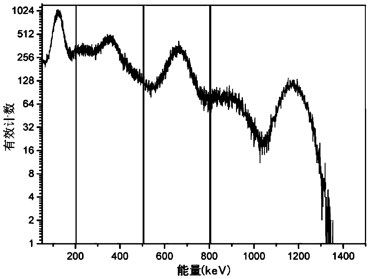
[0077] (1) The common gamma energy range is 50keV-1.5MeV. We also set the energy range that the coded aperture imaging system can detect to 50keV-1.5MeV, and divide the entire energy spectrum in this range into 4 energy windows , are energy window 1: 50-200keV, energy window 2: 200-500keV, energy window 3: 500-800keV, energy window 4: 800-1500keV;

[0078] We open up a memory space for each energy window, assuming that the detector group 4 is a 3×3 array, that is, 9 detectors, then the memory space is also a 3×3 matrix, and the 9 detectors and the memory space The nine elements correspond to each other;

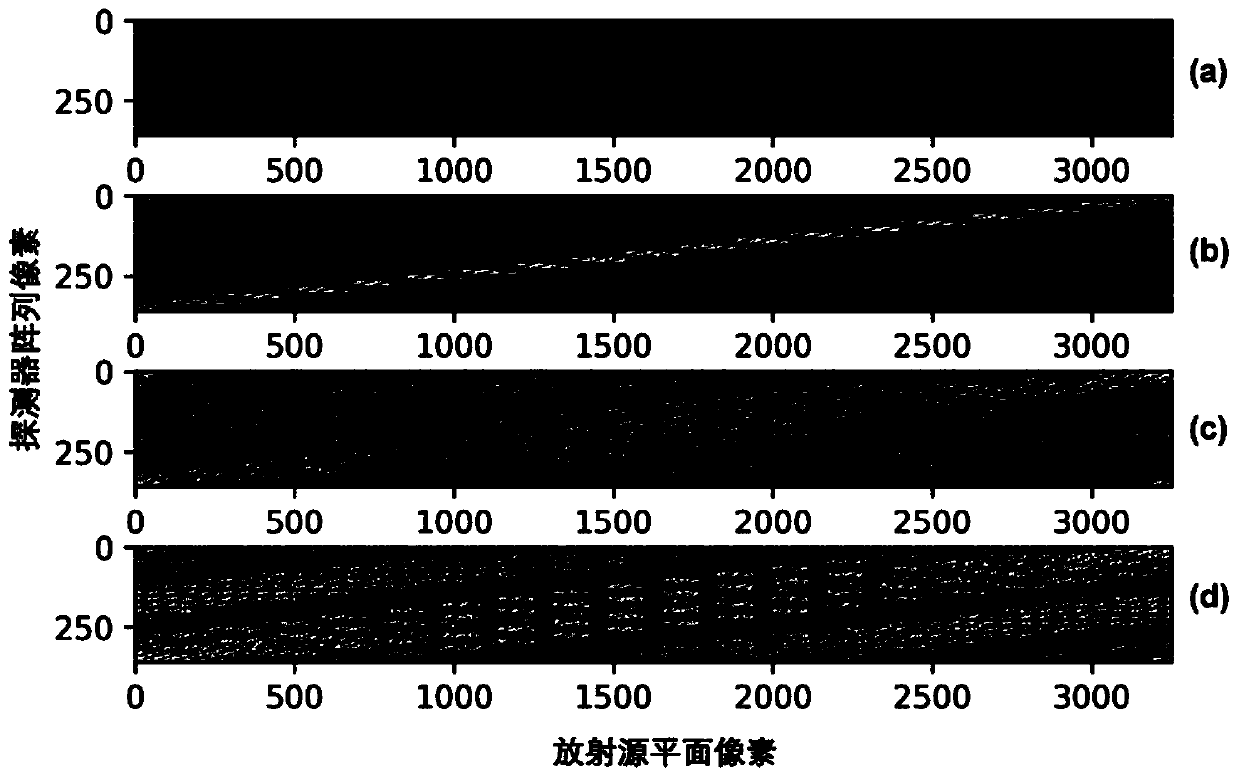
[0079] In each energy window, we have to choose an energy value as the characteristic energy value under the energy window. Here, we respectively take 122keV, 356keV, 662keV, and 1173keV as the characteristic energy...


PUM


Abstract

The invention discloses a radioactive source positioning reconstruction method based on a multi-energy system response matrix. The method comprises the following steps of dividing an energy range detected by a coding aperture imaging system into mutiple energy windows; selecting a characteristic energy value under each energy window; acquiring a system response matrix under a specific energy valueunder each energy window through simulation; during actual measurement, counting measured data according to the energy windows to finally form a plurality of groups of projection data corresponding to the energy windows, then adopting a maximum likelihood expectation maximization algorithm to reconstruct reconstructed images of the energy windows, and adding the reconstructed images under all theenergy windows a to obtain a final reconstructed image. According to the invention, a more accurate system response model is created. The method is suitable for a single-point source, a plurality ofsingle-point sources with the same energy, a plurality of single-point sources with different energy and a shape source, the complex radiation scene can be accurately reconstructed, a reconstructed image with high quality and high fidelity can be provided, and the method is high in transportability and suitable for equipment with different geometric structures and different materials.

Description

technical field [0001] The invention relates to a radiation source positioning method, in particular to a radiation source positioning reconstruction method based on a multi-energy system response matrix. Background technique [0002] In the fields of nuclear facility decommissioning, nuclear waste treatment, nuclear safety and nuclear security, compared with traditional radiation dosimeters, gamma spectrometers and other non-imaging equipment, the coded aperture imaging detection system can realize the spatial distribution imaging of radioactive sources at a long distance Positioning, with excellent angular resolution and detection sensitivity. Among them, high-quality, high-fidelity image reconstruction of the number, activity and distribution of radioactive sources is the basis for providing a strong guarantee for the personal safety of relevant personnel. [0003] The existing coded aperture reconstruction algorithms are mainly divided into two categories: one is linear...

Claims


Application Information

Patent Timeline
Patent Type & Authority Applications(China)
IPC IPC(8): G06T11/00G06T5/50
CPCG06T11/005G06T5/50G06T2207/10084G06T2207/20221
Inventor 庹先国刘崎成毅熊意生
Owner SICHUAN UNIVERSITY OF SCIENCE AND ENGINEERING
Why Eureka
Try Eureka