Method for generating omni-directional circularly polarized vortex electromagnetic waves
A vortex electromagnetic wave and generation method technology, which is applied in the direction of electrical components, electrical digital data processing, special data processing applications, etc., can solve the problems of polarization mismatch, low gain of omnidirectional vortex electromagnetic wave beam, etc., and achieve simple feeding , Low engineering price, high gain effect
- Summary
- Abstract
- Description
- Claims
- Application Information
AI Technical Summary
Problems solved by technology
Method used
Image
Examples
Embodiment 1
[0034] The vortex electromagnetic wave is an electromagnetic wave that carries both spin angular momentum and orbital angular momentum, and has a spiral phase wave front. In the field of communication, the orbital angular momentum carried by vortex electromagnetic waves can be used for information control to greatly increase the channel capacity, which is expected to break through the Shannon limit of channel capacity.
[0035] Compared with ordinary vortex electromagnetic waves, the omnidirectional circularly polarized vortex electromagnetic wave not only has the advantage of large radiation coverage area, but also effectively avoids the application limitation of the divergence characteristics of ordinary vortex waves in the communication field; another On the one hand, its circularly polarized polarization characteristics can effectively avoid the polarization mismatch of linearly polarized antennas, reduce the multipath fading and multipath reflection effects of electromagne...
Embodiment 2
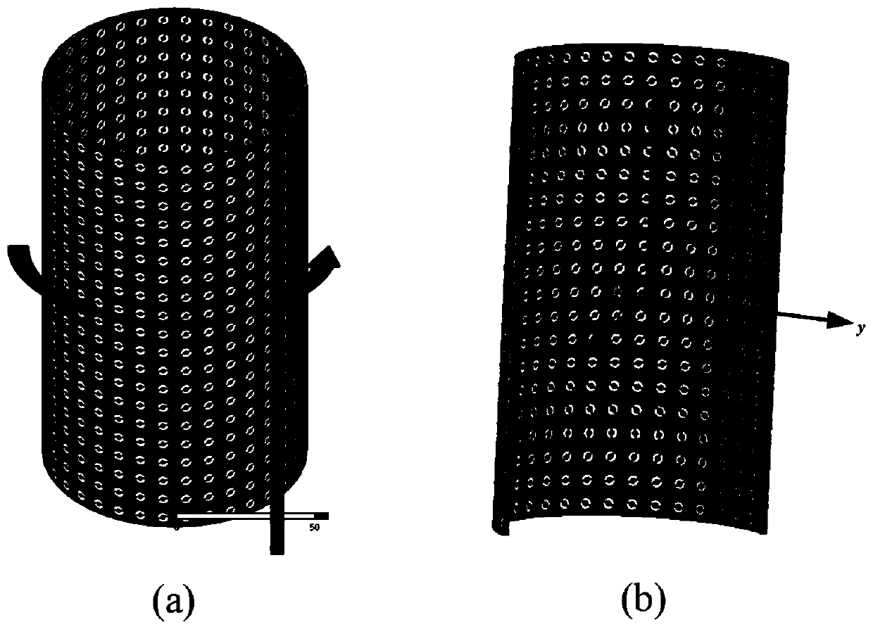
[0053] The generation method of the omnidirectional circularly polarized vortex electromagnetic wave is the same as embodiment 1, the phase distribution of the expected vortex electromagnetic wave of the calculation lens assembly described in step (3), wherein the expected vortex electromagnetic wave phase of the outer surface of the ring cylindrical metasurface lens assembly Distribution, expressed in a mathematical way, assuming that the center coordinate position of the (m, n)th lens unit structure is (x mn ,y mn ,z mn ), then its corresponding expected vortex electromagnetic wave phase The expression of is as follows:
[0054]
[0055] In the formula, L is the orbital angular momentum mode; m is the row number of the transmission unit structure in the toroidal cylindrical metasurface lens assembly, m=1, 2,..., M; n is the transmission unit in the toroidal cylindrical metasurface lens assembly The number of columns where the structure is located, n=1,2,...,N.
[005...
Embodiment 3
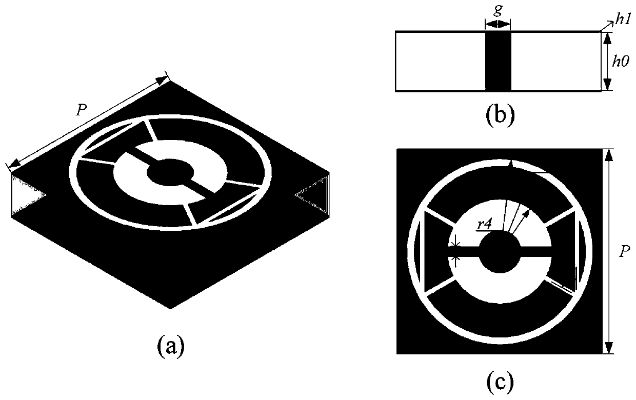
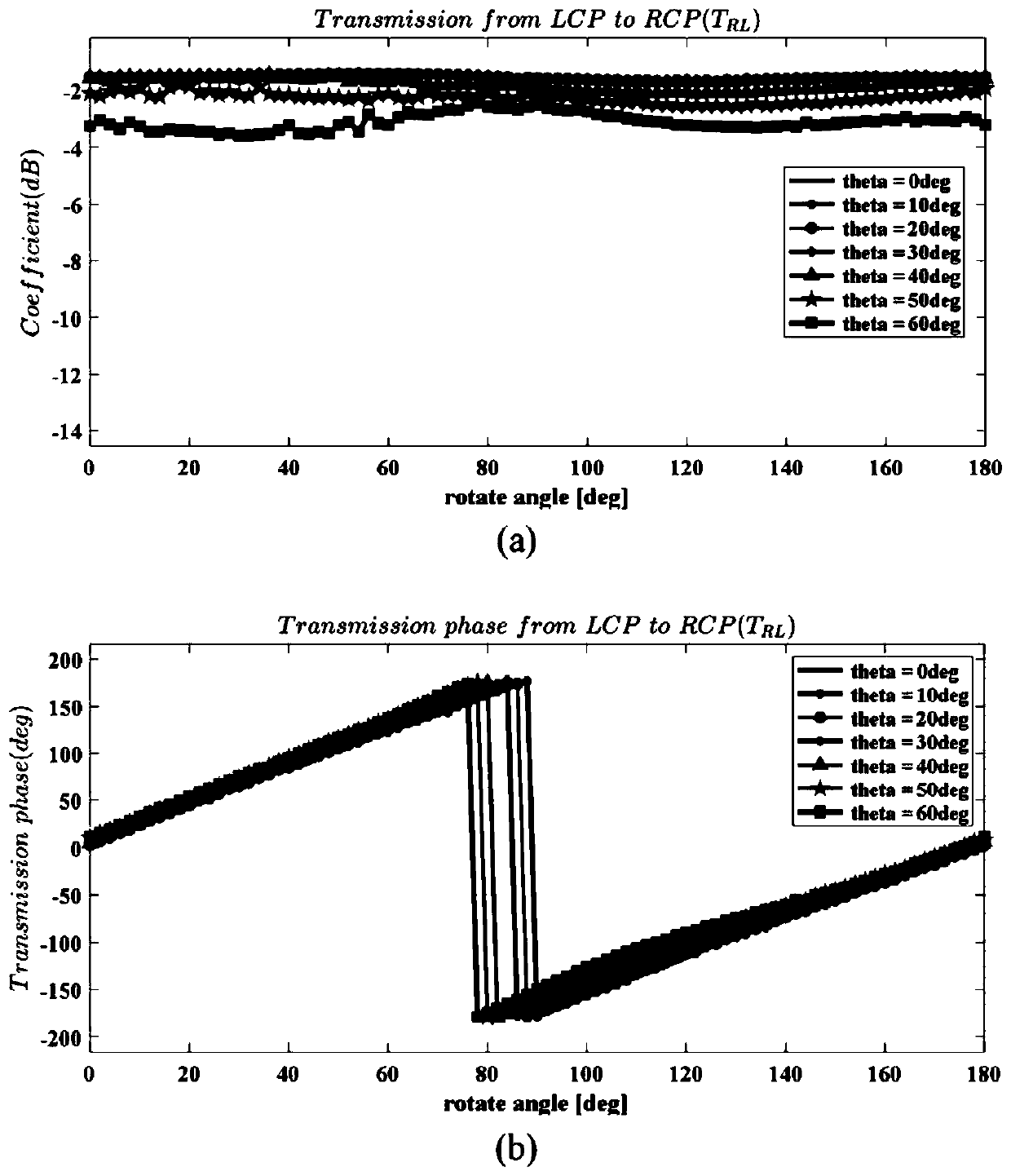
[0058] The generation method of omnidirectional circularly polarized vortex electromagnetic wave is the same as embodiment 1-2, the metal layer geometric rotation angle distribution of the calculation lens assembly initial model described in step (4), wherein the outer surface of the annulus cylindrical metasurface lens assembly initial model The geometric rotation angle distribution of the metal layer of is expressed mathematically as, the geometric rotation angle α of the metal layer in the (m,n)th transmission unit structure mn The calculation formula is as follows:
[0059]
[0060] In the formula, is the expected vortex electromagnetic wave phase on the outer surface of the (m, n)th transmission unit structure in the toroidal cylindrical metasurface lens assembly.
[0061] see image 3 (b), in the relationship curve of the circularly polarized transmission phase of the transmission unit structure with respect to the rotation angle of the metal layer obtained by simu...
PUM
| Property | Measurement | Unit |
|---|---|---|
| Axial ratio | aaaaa | aaaaa |
Abstract
Description
Claims
Application Information
 - R&D
- Intellectual Property
- Life Sciences
- Materials
- Tech Scout
- Unparalleled Data Quality
- Higher Quality Content
- 60% Fewer Hallucinations
Browse by: Latest US Patents, China's latest patents, Technical Efficacy Thesaurus, Application Domain, Technology Topic, Popular Technical Reports.
© 2025 PatSnap. All rights reserved.Legal|Privacy policy|Modern Slavery Act Transparency Statement|Sitemap|About US| Contact US: help@patsnap.com


